Tools
Parts
No parts specified.
-
-
Each LED Strip Assembly comes with pre-installed Pressure Sensitive Hook and Loop Velcro Strips.
-
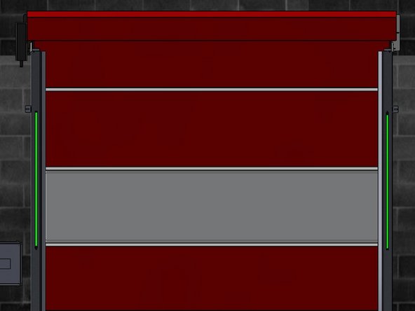
Peel the Clear Backing off each Velcro Strip (6 Total) and stick the LED Strips onto the Vertical Tracks.
-
The LED Strip with the longer cable (25ft) is mounted on the non-drive side of the opening.
-
Ensure the LED Strip is oriented such that the shortest possible length of Cable is needed to reach the Control Panel.
-
The LED Strip with the shorter cable (10ft) is mounted on the drive side of the opening.
-
Ensure the LED Strip is oriented such that the shortest possible length of Cable is needed to reach the Control Panel.
-
DO NOT LENGTHEN EITHER OF THE LED STRIP CABLES AS THIS MAY CAUSE INCONSISTENT PERFORMANCE. THE PROVIDED CABLE LENGTHS ARE IN THEIR 'WORST-CASE' CONFIGURATION.
-
If the provided Cables do not reach the Control Panel, you will need to re-route them, or add a Junction Box to house the Microcontroller (see next step) in a location where both Cables can reach it.
-
-
-
In your Kit, you will also find the following:
-
One Microcontroller.
-
One Power Supply.
-
5-Condcutor Cable to make the necessary Electrical Connections inside the Control Panel.
-
If Receiving this Kit new with your Door, this Cable will be Pre-Installed from the Factory.
-
-
-
Once you have routed the Wires from the LED Strips into the Control Panel, you will have to make a series of Electrical Connections.
-
If receiving this System with your Door Order, the Terminations from the Microcontroller to the Control Panel will be made from the Factory.
-
In a Retrofit Application, you will need to make the Terminal Connections inside the Control Panel from the Jobsite.
-
Find the 5-Conductor Cable.
-
Colors: Green, Blue, Red, Yellow, White
-
-
-
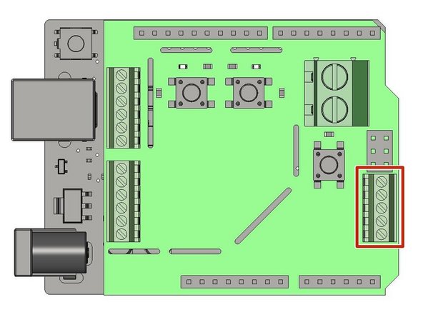
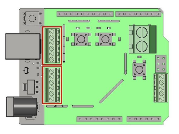
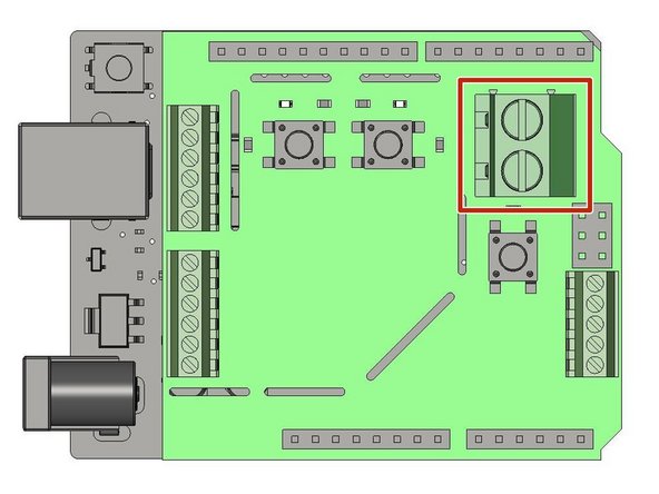
Located the J3 Terminal Block
-
Note the Orientation of the Microcontroller in the Diagram.
-
Make the following Connections on the Microcontroller (from Top to Bottom) using the 5-Conductor Cable:
-
White, Yellow, Red, Blue, Green
-
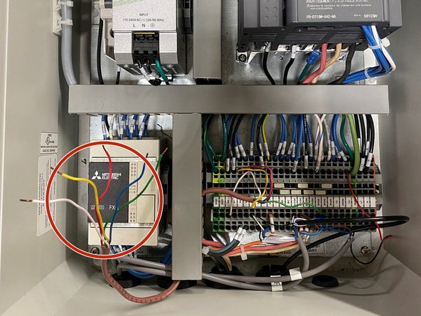
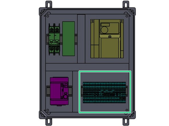
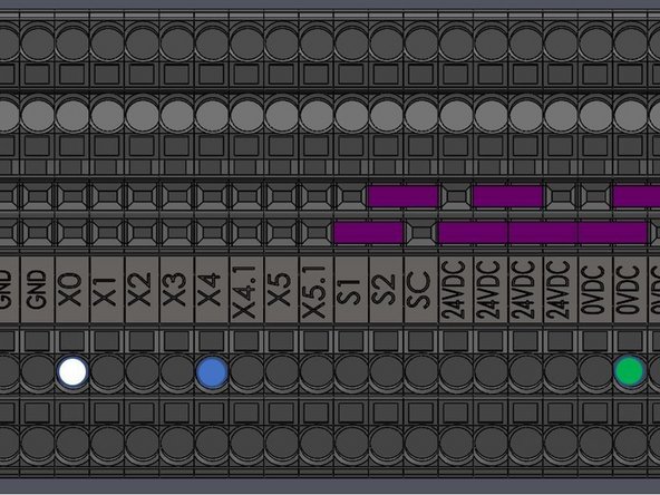
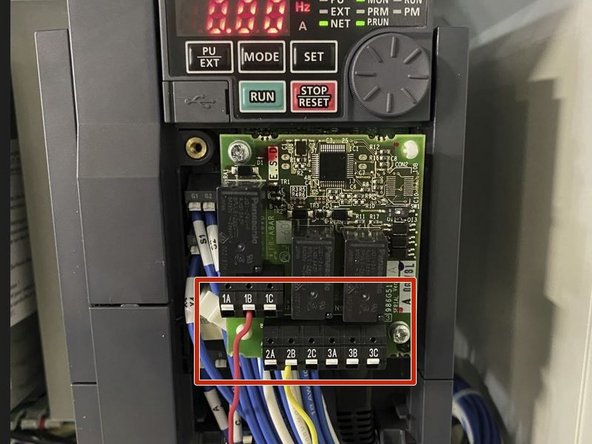
On the other end of the 5-Conductor Cable, 3 of the wires Terminate in the Control Panel as seen in Images 2 and 3.
-
All Terminals Vertically Aligned are Electrically Identical.
-
Multiple Wires can be placed in the same Terminal.
-
-
-
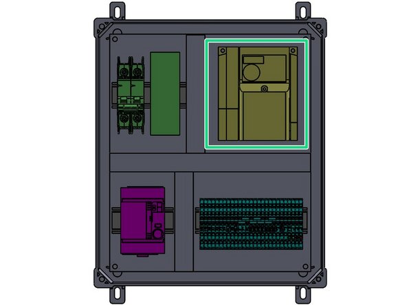
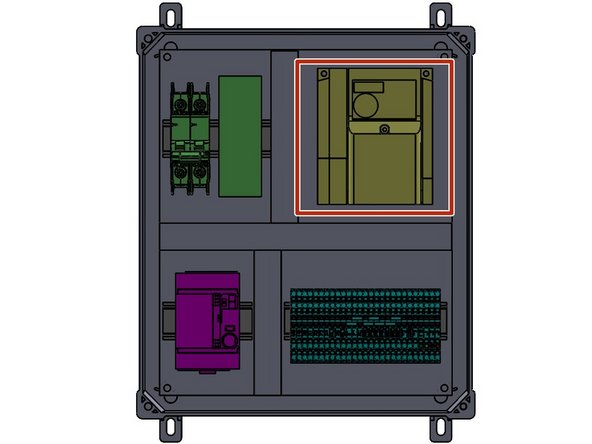
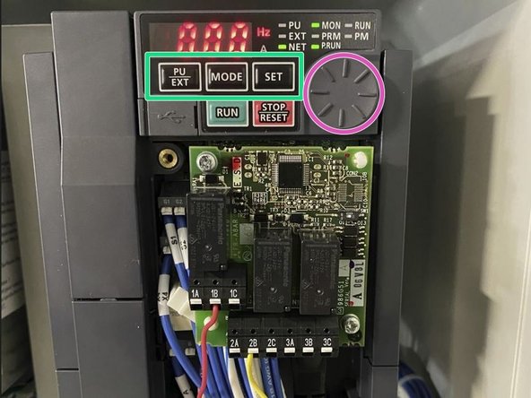
In the Upper-Right Corner of the Control Panel, Locate the VFD. Remove the Cover with the single Screw on the Front.
-
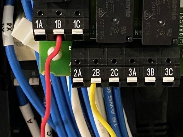
The remaining 2 Wires (Red and Yellow) that were not wired into the Terminal Block will be landed on the VFD as seen in Images 2 and 3.
-
Red Wire in Terminal 1B (Image 3)
-
Yellow Wire in Terminal 2B (Image 3)
-
In a Retrofit application, you will need to run (2) additional wires:
-
Between 24VDC on the Terminal Block and 1C.
-
Between 24VDC on the Terminal Block and 2C.
-
Replace the Cover Removed at the Beginning of this Step.
-
-
-
Bring the (2) 3-Conductor Cables from the LED Strips into the Control Panel.
-
Locate the J6 and J7 Terminal Blocks
-
Note the Orientation of the Microcontroller in the Diagram.
-
Each Terminal Block receives Wires from One of the LED Strips.
-
Make the following Connections (from Top to Bottom) on each Terminal Block:
-
Red, White, Empty, Empty, Empty, Black
-
-
-
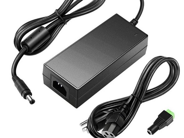
Locate the Provided Power Supply.
-
Bring Power (Single-Phase 120 to 240VAC) to the Power Supply via the Plug or by Hardwiring.
-
Power can come from an Outside Source, or can be pulled from the Supply that is feeding your Control Panel.
-
Make sure Electrical Requirements can be fulfilled without straining the System.
-
-
-
Cut the Barrel Connector off of the Output Side of the Power Supply.
-
Bring the Power Supply Output into the Control Panel.
-
Locate the J9 Terminal Block
-
Note the Orientation of the Microcontroller in the Diagram.
-
Make the following Connections (from Top to Bottom):
-
Red, Black
-
-
-
Before we can Program our LED Door Indicator Light System, we must set up the Time-to-Close (TTC) Feature on our Control Panel.
-
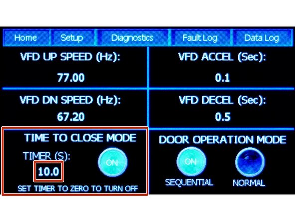
To Turn On and Adjust the Timer: Press the number (10.0 in picture) below "Timer (s)" text. A Pop-up Keypad is displayed.
-
Seconds from 0.0 to 60.0 are valid entries.
-
Set the timer to "0" to Turn Off the Auto-Close Timer/Function.
-
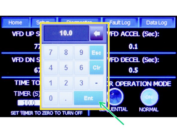
In the Numerical Keypad, Enter the Desired time in Seconds before you want the Door to Automatically Close.
-
Press "ENT" to save your Timer Delay.
-
Interrupting/Breaking the Photo-Eye/Safety-Sensor Beam will reset the Timer to the preset Time.
-
-
-
When first Powered On, the LED Strips will Flash Green for One Second. At this Point, Proceed to the
-
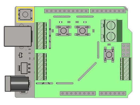
If at any point, you need to Restart the Programming Sequence, Press the 'RESET' Button.
-
When the 'RESET' Button is Pressed, the LEDs will Flash Green for One Second. When the Green turns Off, you are ready to Begin the Programming Process.
-
-
-
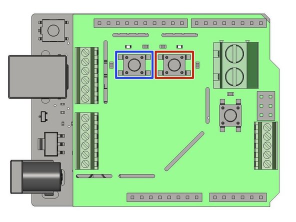
Locate the Blue Button Labeled SW1
-
Each Press of this Button adds One Second to the Timer associated with the LED Light System (10 Presses = 10 Seconds).
-
To Sync the LED Light System with your Control Panel, you must Press SW1 One time for every Second Programmed on your Control Panels' TTC Feature.
-
If your TTC is set for 10 Seconds, you must Press SW1 Ten times.
-
Locate the Blue Button Labeled SW2
-
Once you have Synced your LED Light System with your Control Panel by Pressing SW1, Press the SW2 Button One time.
-
This Locks in your Programming, and Initiates the Light System's Operation.
-
-
-
Locate the VFD in the Upper-Right corner of the Control Panel.
-
Press the PU/EXT Button Once, and then the Mode Button Once.
-
Turn the Rotary Dial Until you see "P. 320",
-
Hit the Set Button Once.
-
Turn the Rotary Dial Until the Value of that Parameter is "9999"
-
Hit the Set Button Once.
-
Repeat Steps 3-6 for P. 321 and P.322
-
Press the PU/EXT Button Once, then the Mode Button Twice to Exit the Parameter Menu. Your Door is ready to Operate with the LED Indicator Lights.
-


