Tools
Parts
-
-
Sick Sensor Kits (x2)
-
The RFID Tags will be Mounted to the Vinyl Panel just Above the Bottom Wind Bar upon Receipt
-
Wires, Cables, and Connectors Included
-
Sensor Mounting Brackets (x2)
-
All Necessary Fasteners
-
(2) 6-32 x 3/4" Long Phillips Head Screws
-
(2) 6-32 Nylon Lock Nuts
-
(2) #14 x 1/2" Phillips Head Sheet Metal Screws
-
-
-
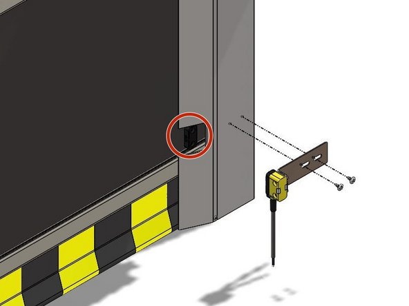
Insert the 6-32 x 3/4" Screws Through the Sensor so that the Screw Heads sit Recessed in the Sensor Housing.
-
See Exploded View
-
Noting the Orientation of the Bracket, Place the Bracket onto the Screws and Secure with the 6-32 Nylon Lock Nuts.
-
-
-
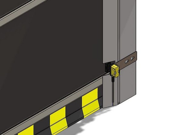
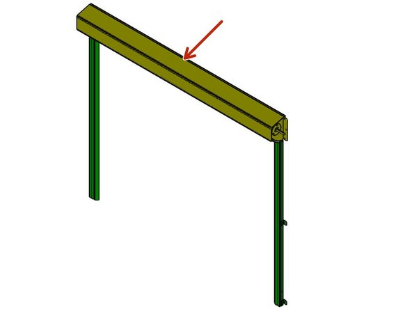
With the Door in the Closed Position, you will see the RFID Tags Mounted to the Vinyl Panel just above the Bottom Wind Bar through Cutouts in the Rubber Weather Seal.
-
Make Sure the Close-Limit is set Appropriately BEFORE Mounting the Sensors.
-
Using the #14 x 1/2" Sheet Metal Screws, Mount the Sensor and Bracket Assembly at a Height that Aligns the Sensor with the RFID Tag.
-
It is Best to Drill Small Pilot-Holes First.
-
There are Slots in the Mounting Brackets to allow Adjustment of the Sensors In/Out and Left/Right.
-
-
-
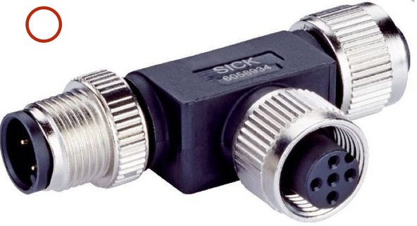
(2) T-Junctions
-
Each T-Junction contains (1) Male 5-Pin Connection, (1) Female 5-Pin Connection, and (1) Female 8-Pin Connection Point.
-
(1) 5-Pin End Connector MLP1-XXT
-
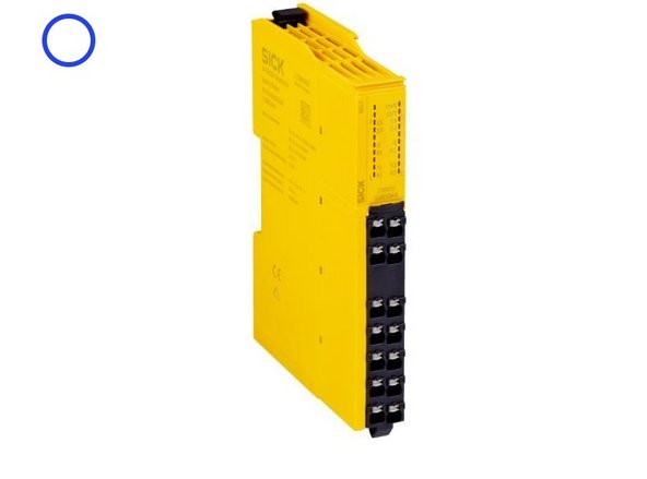
(1) Relay
-
(2) Dual 8-Pin Connector Cables
-
(2) Dual 5-Pin Connector Cables
-
(1) 5-Pin to 4-Wire Cable
-
-
-
It is Best to Locate T-Junction #1 Somewhere between Sensor 1 and Sensor 2.
-
A Good Spot is above the Header
-
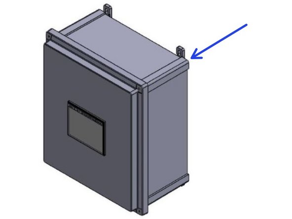
It is Best to Locate T-Junction #2, as well as the Relay, Inside of the Control Panel.
-
Route the Cables Up and Around Using the Door to Secure them Every Few Feet.
-
-
-
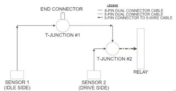
All Connections between Sensors, T-Junctions, and End-Connectors are Screw Connections. There will be only 4 Wired Connections. Two at the Relay, and Two at the Terminal Block within the Goff's Control Panel.
-
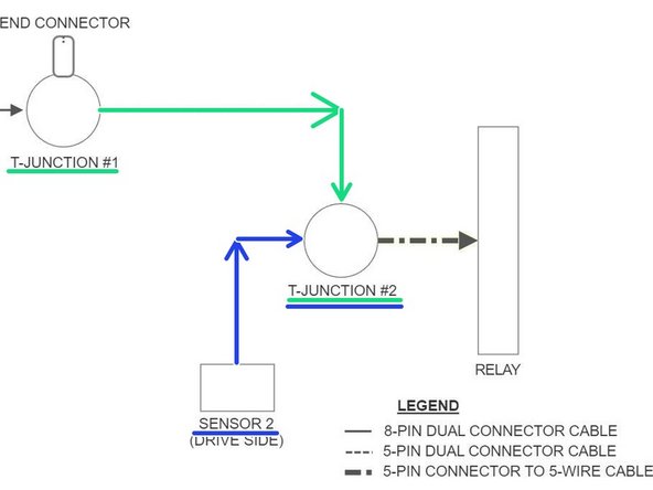
See the Basic Layout in Image 1.
-
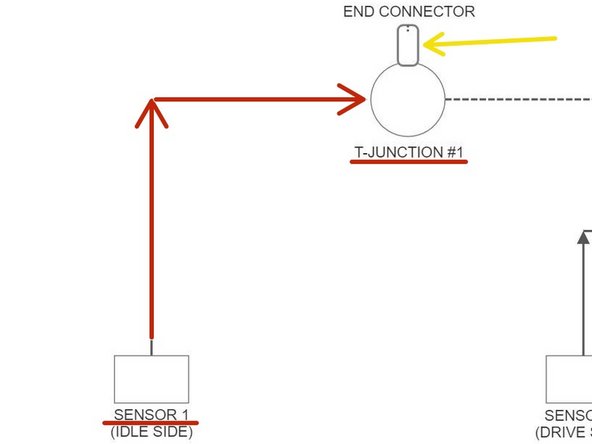
Connect Sensor 1 (Idle Side) to T-Junction #1 with an 8-Pin Dual Connector Cable.
-
Screw the 5-Pin End-Connector onto T-Junction #1.
-
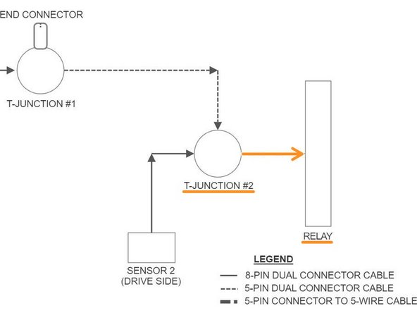
See Image 2.
-
Connect T-Junction #1 to T-Junction #2 with a 5-Pin Dual Connector Cable.
-
Connect Sensor 2 (Drive Side) to T-Junction #2 with a 5-Pin Dual Connector Cable.
-
See Image 3.
-
-
-
Connect T-Junction #2 to the Relay with the 5-Pin to 4-Wire Cable.
-
Screw the 5-Pin Connector onto T-Junction #2.
-
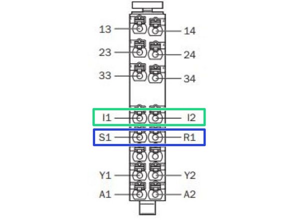
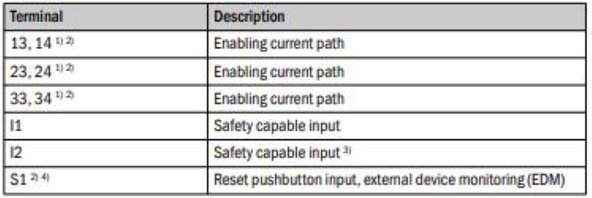
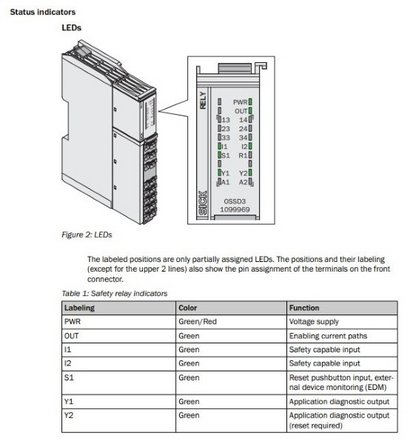
On the Relay, Using the Bare-Wire End of the Cable, Connect the White Wire to I1, and the Black Wire to I2.
-
On the Relay, Put a Jumper Wire between S1 and R1.
-
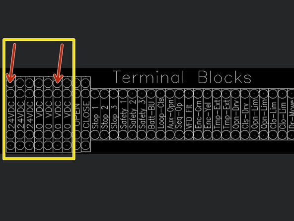
On the Terminal Block Inside your Goff's Control Panel, Connect the Brown Wire to 24VDC, and the Blue Wire to 0VDC.
-
-
-
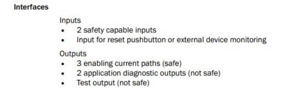
To Integrate Industrial and/or Automation Equipment, Connect to Terminals:
-
13 and 14
-
23 and 24
-
33 and 34
-
These are Safe Circuits, controlled by the Sensors previously Installed, that can Turn Equipment On/Off Based on the Status of the Sensors and their Circuits.
-
For More Information, Please Read the Manuals that are Included with the Sick Sensor Kits.
-


