
-
-
Technical Support Contacts:
-
Phone: 262-746-3374
-
Email: techsupport@goffscw.com
-
Website: http://www.goffsenterprises.com
-
-
-
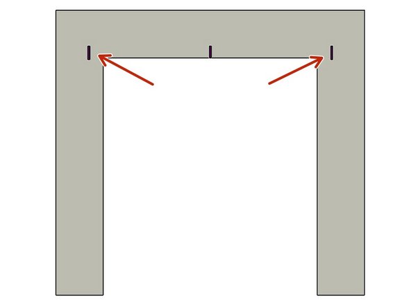
Measure the Opening Width near the top of the Opening.
-
Divide that overall width measurement in half to find the Centerline location.
-
Clearly Mark the Centerline location.
-
-
-
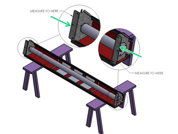
The Header Measuring Process is identical for all Door Models. The Door Model you are installing may be different from the Model shown.
-
Place the Door roll Header Assembly across a safe and level work surface, and rotate the roll assembly frame so that the Header Bracket Mounting flanges are facing upward.
-
Measure the total width of the whole roll assembly from outermost edge of one Header Bracket’s Mounting flange to the outermost edge of the opposite side.
-
Divide that number by 2. This number is 1/2 of the Header Width, and is used to determine the Header location on the Left and Right Sides of the opening.
-
-
-
Mark this dimension on each side of the Opening Center mark.
-
-
-
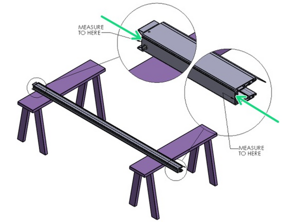
Lay one of the Vertical Track Assemblies on your work surface.
-
Measure the Length of the Aluminum Track only.
-
Add 1/4" to the Track dimension.
-
This is the Height dimension needed to mark the location of the Bottom edge of the Header Mounting Brackets.
-
-
-
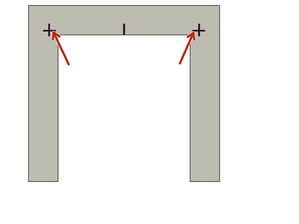
Add a Horizontal line on each side of the Opening that intersects the previously drawn Vertical line.
-
-
-
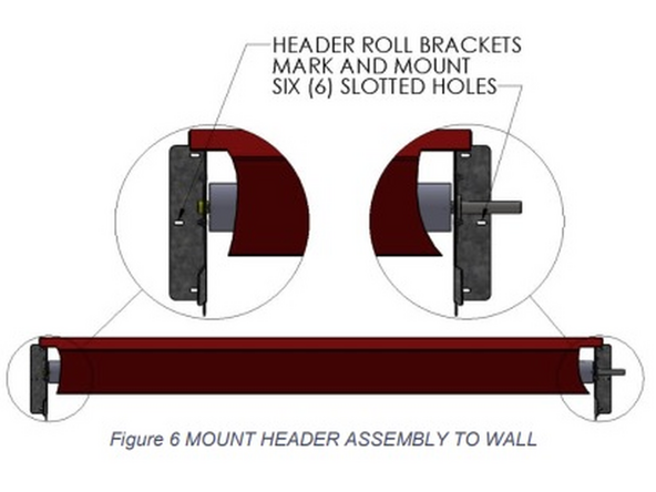
Using two (2) people, and two ladders at minimum, raise the Roll Header Assembly to fit between, and above, your markings on the wall.
-
Trace the insides of the Header Bracket’s three (3) mounting slots onto the wall surface.
-
Be sure that the Mounting Bracket’s bottom edge is on the height line, and that the outer edge is on your vertical/width line.
-
Predrill pilot holes for the mounting hardware at the centers of the traced locations. Using adequate mounting screws or bolts (depending on your building/surface material) to attach the Roll Header Bracket to each side of the opening.
-
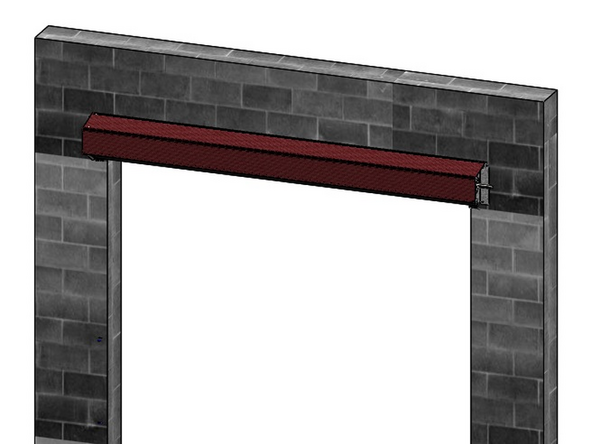
Raise the Roll Header Assembly into place on the wall, and loosely secure with three (3) sets of mounting hardware per side using screws or bolts that are adequate to your building/surface material.
-
Check the Header Assembly for level, and fully tighten all six sets of hardware.
-
At this point leave the Roll Assembly tied off and held in place as it comes.
-
-
-
If you would like to mount the optional Track Extensions, please refer to the supplemental Track Extension installation instruction before proceeding. If not, proceed to the next step.
-
-
-
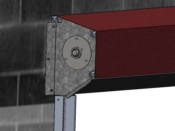
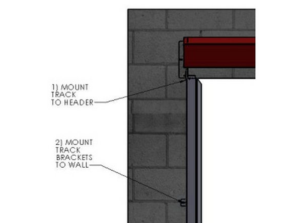
The Track mounts to the Outside of the Tab of the Header Mounting Bracket.
-
It is important to insert the Carriage Bolt from the Inside of the Header Bracket, and to install the Washer and Hex Nut on the Outside of the Track.
-
The Track must be plumb before securing it to the Mounting Surface.
-
-
-
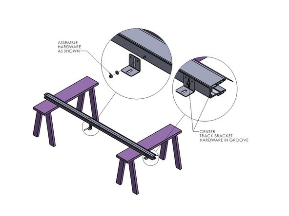
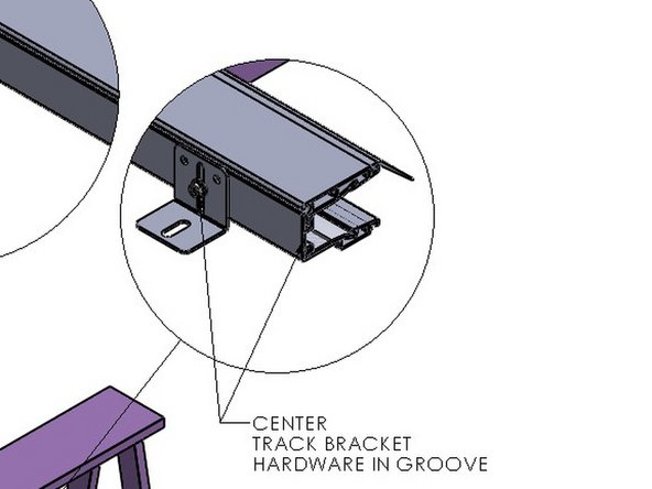
Attach a Track Mounting Bracket to the Track in the hole located at the bottom.
-
NOTE: For extreme cases, such as “High Wind Loads”, an additional Track Mounting Bracket (supplied) will be necessary.
-
Mark and Drill the Track (.28-.31 dia) at 1.44” in from the front edge (i.e. centered in the groove), at about mid-height of the Track.
-
-
-
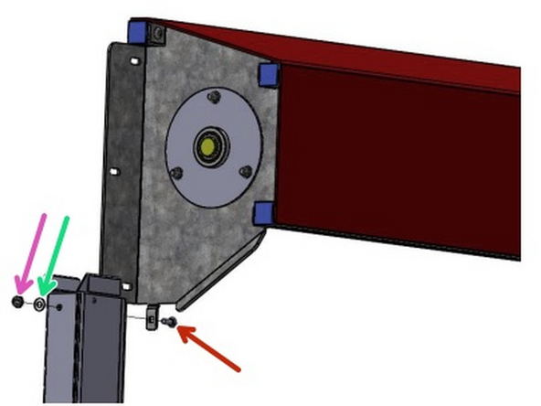
The Track assembly mounts to the outside of the tab of the Header Assembly Mounting Bracket.
-
Insert the Carriage Bolt through the Header Bracket Tab from the inside.
-
Move the Track to the Outside of the Header Bracket, then push the Bolt fully through the Square hole in the Tab and the Track.
-
Slide the Washer onto the Bolt from the outside of the Track.
-
Then snug the Hex Nut on the Bolt.
-
-
-
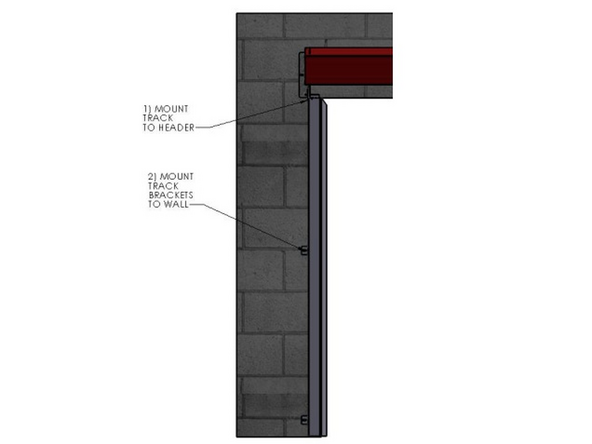
Plumb each Track.
-
Fasten the Tracks to the Mounting Surface through the Mounting Brackets.
-
Keep the Material and Roll-Tube tie wrapped until the Motor is Powered and ready to have the Limits Set.
-


Team
