
Featured Document
-
-
The external operator requires 115VAC, 60Hz with a current draw of 5A (1/2 HP PSC inductive motor).
-
Make sure that the branch circuit and conductor size can support this load requirement.
-
Low voltage can cause erratic behavior and operator overheating.
-
A Spring Assist mechanism is Factory installed on Larger doors. On the Idle end of the Roll-Tube, a Hitch Pin, and a Tag are Factory installed. This PIN MUST REMAIN INSTALLED during the Normal Operation of the Door.
-
If removing the Pin becomes necessary, the Door MUST BE OPEN FULLY to discharge the Torsion Spring. Removing the pin when the door is closed or partially closed may cause Personal Injury and damage to the Door System.
-
The Pin should only be removed for maintenance/service purposes, and ONLY when the door is in the Fully Open position. Removing the pin when the door is closed or partially closed may cause damage to the system and personal injury.
-
-
-
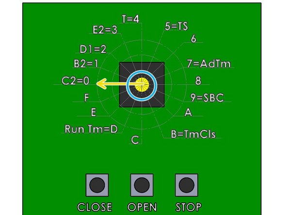
Before making adjustments to the Dial, Ensure that the Stop Button is Closed. The Close Limit Indicator Light should be illuminated.
-
Locate the rotary selector switch on the printed circuit board.
-
Set the Dial to C2=0.
-
-
-
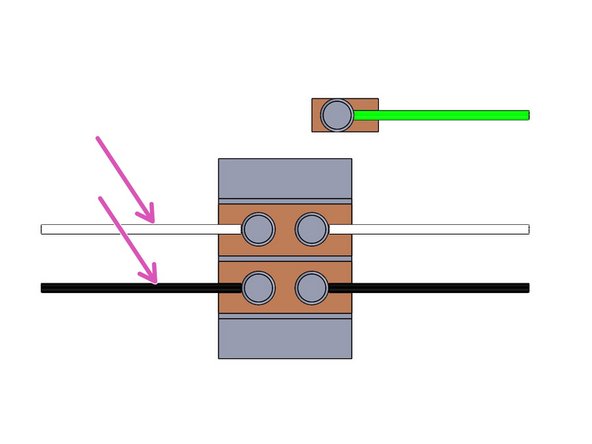
Make the following Line-In connections.
-
Neutral - White
-
Line - Black
-
Ground - Green
-
Factor Wired
-
-
-
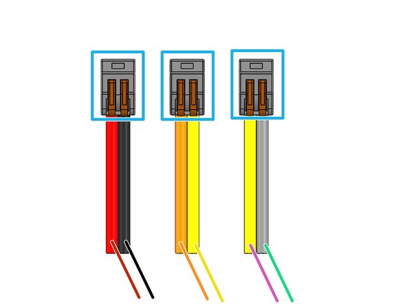
Factory Installed Splices
-
Red - Motor Control - Field Wire
-
Black - Hand Crank Safety - Factory Wired
-
Orange - Motor Control - Field Wire
-
Yellow - Thermal Loop - Factory Wired
-
Yellow - Thermal Loop - Factory Wired
-
Gray - Hand Crank Safety - Factory Wired
-
-
-
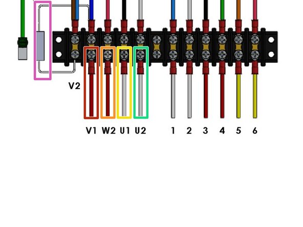
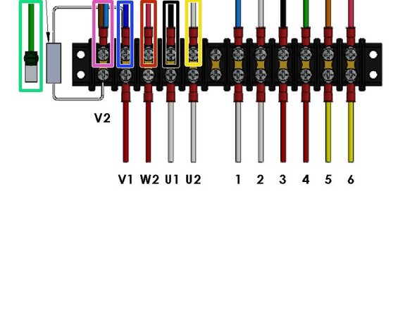
33K Ohm Resistor - Factory Installed
-
Red - V1
-
Red - W2
-
Yellow - U1
-
Yellow - U2
-
-
-
Is this image used in the Instruction?
-
White -
-
Red -
-
Yellow -
-
-
-
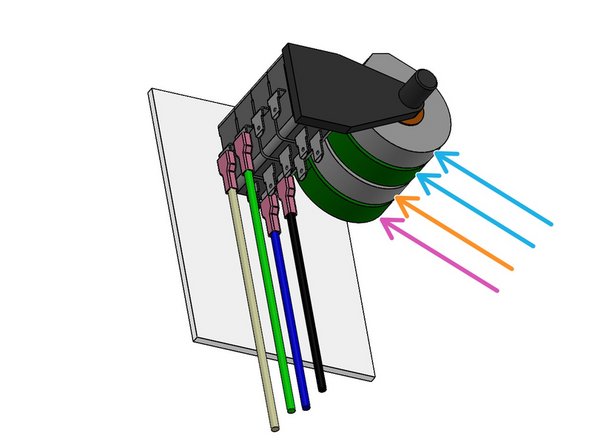
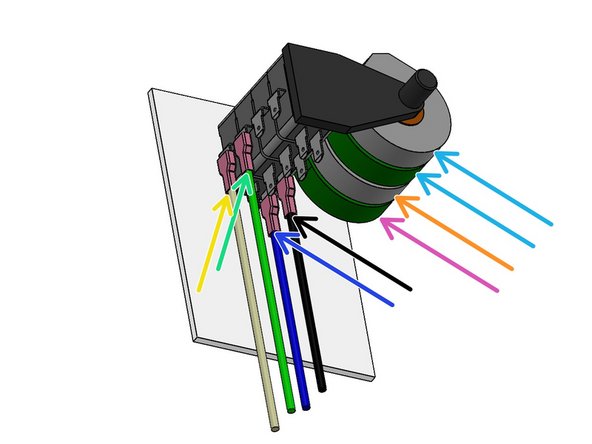
Green - to Motor Chassis Ground
-
Brown - From Capacitor
-
Blue to Motor Red
-
Blue - from Capacitor
-
Red - to Motor Red/ Black stripe
-
Black - to Motor White/Black stripe
-
White - to Motor White
-
Run this Thermal Cable to the Motor
-
-
-
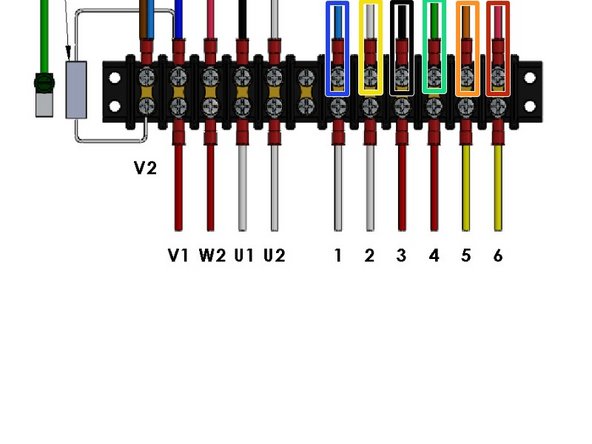
Use the 6-Conductor "Control Cable" (Included) to make these Limit Control Connections
-
Blue - to Open Limit N/C
-
White - to Open Limit COM
-
Black -to Close Limit N/C
-
Green - to Close Limit COM
-
Orange - Yellow from Thermal Loop
-
Red - to Black from Hand-Crank Safety Switch.
-
-
-
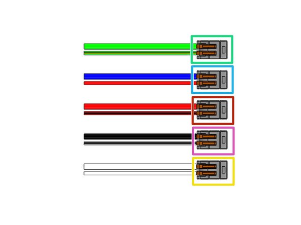
Green - & Green/Yellow: Green Motor Ground Wire & Green/Yellow Motor Chassis Ground
-
Blue & Red: Blue Motor Power Wire from V1 & Red Motor Winding Wire
-
Red & Red/Black: Red Motor Power Wire from W2 & Red/Black stripe Motor Winding Wire
-
Black & White/Black stripe: Black Motor Power Wire from U1 & White/Black stripe Motor Winding Wire
-
White & White: White Motor Power Wire from U2 & White Motor Winding Wire
-
-
-
Open and Close Door Limits are set by rotating the Cam associated with a Limit Switch for that function.
-
Our Standard is to use the innermost pair of Cams/Switches.
-
Backup Limit Switches (Not used)
-
Close Limit Cam/Switch
-
Open Limit Cam/Switch
-
-
-
See 1st Page for Cautions and Notes
-
Locate the 6 conductor wire marked "Control".
-
-
-
Use 6 Conductor "Control" Wire to make these connections at the External Motor.
-
Close Limit Motor Control Wires:
-
Black on Bottom Terminal
-
Green on Front Terminal
-
Open Limit Motor Control Wires:
-
Blue on Bottom Terminal
-
White on Front Terminal
-
Cams/Switches are Not used
-
-
-
Use 6 Conductor "Control" Wire to make these connections at the External Motor.
-
Blue - to Open Limit N/C
-
White - to Open Limit COM
-
Black -to Close Limit N/C
-
Green - to Close Limit COM
-
-
-
What image is needed? what title for the step???????????????????
-
Orange from 6 conductor to yellow thermal protection wire
-
Red from 6 conductor to black from hand crank safety switch
-
-
-
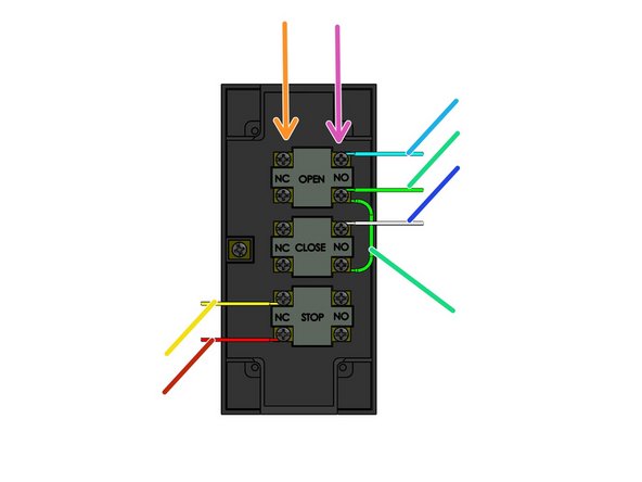
The RCS Controller supports 3-Button Control Stations with N/O (Normally Open) OPEN and CLOSE Buttons.
-
The “Stop” buttons must be N/C.
-
The Low-Voltage Control Connections for the Secondary Station should be made with the 5-Conductor Wire (included the Wiring Kit).
-
Single-station control installations are performed by simply running the control wiring between the Control Station and the Operator, and attaching the appropriate wires to the screw Terminals (Below).
-
Additional Control Stations, Pull Cord and RF Interfaces can be added.
-
-
-
Green - 8 COM
-
Red - 9 STOP
-
Blue - 7 OPEN
-
White - 6 CLOSE
-
White - 6 CLOSE
-
-
-
Brown - 24Vac 1 (Power)
-
Blue - 24Vac 2 (Power)
-
Black - SENS 5
-
White - COM 3
-
Gray - Not Used
-
-
-
All programming changes on the operator must be made with the door in the fully closed position!
-
Verify that the door is fully closed and that the close LED is illuminated.
-
The Maximum Run Timer (MRT) protects the Door and the Operator from damage, should there be a bind or other problem, by limiting the amount of time that the Operator will run continuously.
-
-
-
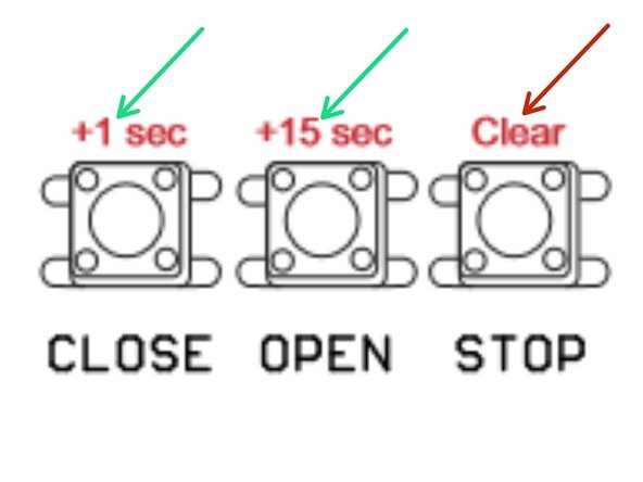
To program the delay time, press the corresponding on-board buttons to get to the desired time.
-
Each press of a Button adds its specified time: Close Button = +1 sec., Open Button = +15 sec.
-
For example, Pressing the "OPEN" button 3 times, will result in a 45 second delay before closing the door.
-
-
-
Fully close the door and verify that the Close LED is illuminated
-
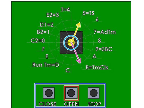
Use the Rotary Switch for the following steps:
-
Set the Dial to B=TmCls
-
Press the STOP button on the controller to reset delay time to 0
-
Set the desired Delay Time - 1 Sec/15 Sec (Press multiple times to increase the Delay Time)
-
To Enable the TTC Mode turn the Rotary Switch to 5=TS
-
To disable the TTC mode (without altering the programmed delay time), fully close the Door and set the Rotary Switch to the B2=1 Position.
-
To Re-Enable by turn the Rotary Switch to 5=TS Position when the Door is fully closed.
-
-
-
To Dis-Able for one Cycle:
-
Press:
-
STOP, STOP, STOP
-
CLOSE, CLOSE, CLOSE
-
-
-
Additional hard-wired control stations can be added to your external operator system.
-
There is no limit to the number of stations that can be attached to the unit.
-
The first (primary) control station is wired to the operator with 5-Conductor Wire.
-
The “Open” and “Close” buttons on your control stations are N/O (Normally Open) and must be wired in PARALLEL.
-
The “Stop” buttons are N/C (Normally Closed) and must be wired in SERIES (daisy chain).
-
-
-
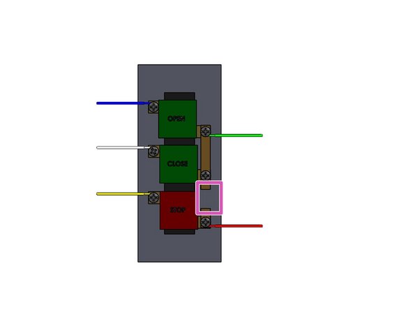
Remove the Cover of the Push Button Stations
-
Cut the bonding strip between the Close and Stop button terminals. This is required only when??????????????
-
Make the following Connections:
-
Blue - Open
-
White - Close
-
Green - Common
-
Red - STOP
-
Yellow - Stop Return
-
-
-
Normally Closed Terminals
-
Normally Open Terminals
-
Green - Common; also Jump wire from N/O OPEN to N/O CLOSE
-
Red - N/C STOP
-
Yellow - Stop Return
-
Blue - Open
-
White - Close
-
-
-
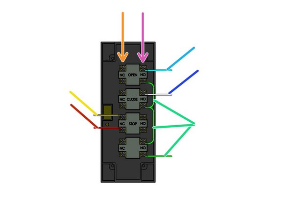
Normally Closed Terminals
-
Normally Open Terminals
-
Green - Common on N/O LOCK; also Jump wire from N/O OPEN to N/O CLOSE; also Jump wire from N/O CLOSE to N/O Lock
-
Red - STOP
-
Yellow - STOP Return
-
Blue - OPEN
-
White - CLOSE
-
-
-
Route the cable through one of the station knockouts and carefully reinstall the cover.
-
Make sure that the cover is installed properly and that the buttons work freely.
-
The other end of the 5-Conductor Wire is attached to the control terminals at the external operator.
-
The White (Close) wire will connect to Terminal #6.
-
The Blue (Open) wire connects to the same terminal as the blue wire from the primary control station (Terminal #7).
-
The Green wire (Common) connects to Terminal #8.
-
-
-
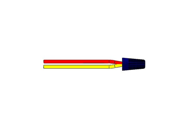
At the Primary Control Station, disconnect the Red wire from the from Terminal #9.
-
Connect this Red Wire with the Stop Return Yellow Wire of the Station being added (5-Conductor bundle). Use the included blue wire nut to fasten them together.
-
Connect the red wire for the new station to Terminal #9.
-
Continue to add control stations by following this same procedure.
-
Connect the blue, white, and green wires to the corresponding terminals in the operator.
-
Disconnect the red wire from the previous station from the #9 Terminal, connect it to the yellow wire for the new station (wire nut).
-
connect the red wire for the new station to Terminal #9.
-
-
-
The External Operator supports N/O (Normally Open) Pullcord Switches, N/O Single Button Control Stations, and any other N/O dry contact.
-
All N/O switches should be wired in PARALLEL and the wiring junctions can be made either at the switches (daisy-chain) or at the External Operator (Homerun).
-
Switches should be connected using two-conductor wiring (supplied) and terminated at the External Operator at the #3 (COM) and #4 (O/C) terminals.
-
Color codes are not important.
-
On the Switch, terminate the Control Wires on both N/O Terminals.
-
-
-
Transmitter:
-
Brown +24VDC
-
Blue -24VDC
-
-
-
Receiver:
-
Brown +24VDC
-
Blue -24VDC
-
Yellow - Common
-
Black - SENS (N/O Signal Wire)
-
White - Not used
-
-
-
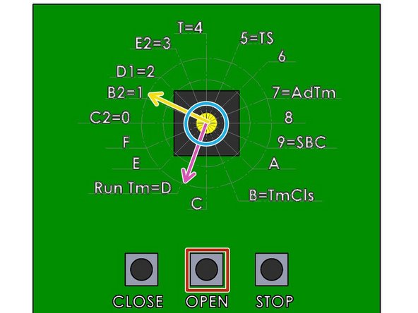
Proceed through the Steps as quickly as possible to ensure a successful change in function.
-
This process will change the Controller from “Constant Pressure to Close” (C2- Configuration) to “Momentary Pressure to Close” (B2-Configuration).
-
View of the Printed Circuit Board
-
Use the Rotary Switch for the following steps:
-
Turn the Switch to the “D” (Run Tm) position.
-
Press the “Open” button and allow the door to reach the fully opened position. The MRT is now set.
-
Turn the Switch to the “1” position.
-
-
-
Device is supplied with Single and Double Gang Box Covers, but without an Electrical enclosure.
-
Red +24VDC
-
Black 0VDC
-
White Common
-
Green Open N/C Signal WIre
-
Yellow is not used
-
-
-
Sensitivity Potentiometer: Adjust Detection Field from 4-24" (Rotate Clockwise to Increase).
-
Hold Time Potentiometer: Adjust Relay Hold Time from .5-30 Sec. (Rotate Clockwise to Increase).
-
Output Mode Switch: Determines Toggle Mode or Timer Mode.
-
Toggle (Switch Up): Detection Activates the Relay. Relay holds until Second Detection which De-Activates the Relay. (Switch Applications)
-
Timer (Switch Down): Detection Activates the Relay for .5-30 Sec. Relay will Hold as long as Detection occurs.
-
LED Mode Switch: Toggles LED to illuminate when in Detection, or not in Detection.
-


Attached Documents
Team
