
-
-
Sensitivity Potentiometer - Used to adjust the Detection Field. Range 4"-24". (Factory set at 4", setting is fully CCW)
-
Hold-Time Potentiometer - Used to adjust the Relay Hold Time. Range .5 sec. - 30 sec.. (Factory Setting .5 sec., setting is fully CCW)
-
Output Mode Switch - Used to set either Toggle Mode or Timer Mode. (See descriptions below.)
-
Output Mode Switch in Toggle Mode (Switch Up) (Recommended for Switch applications)- Detection activates the Relay and the Relay holds until a second Detection De-activates the Relay.
-
Output Mode Switch in Timer Mode (Switch Down) (Factory Setting)
-
LED Mode Switch - Used to set LED to Illuminate when the Sensor is in Detection., or when not in Detection.
-
LED Mode Switch Up (Factory setting) - The LED is Off when the Sensor is in Detection.
-
LED Mode Switch Down - The LED is On when the Sensor is in Detection.
-
-
-
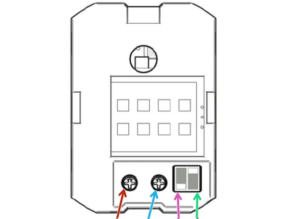
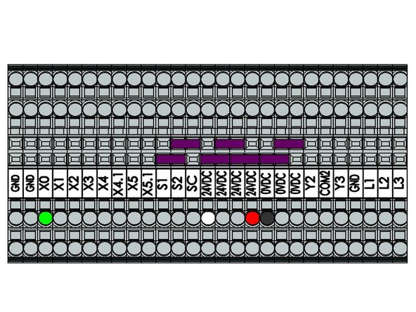
0 VDC - Black
-
24 VDC - White
-
24 VDC - Red
-
X0 - Green
-
-
-
The yellow wire is used only in Normally Closed (NC) wiring applications. The Goff’s standard is Normally Open (NO) wiring for all activation devices, and therefore does not utilize the yellow wire.
-
This device comes with a Cover Plate that will fit a Single or Double Gang Electrical Box.
-
An Electrical Box is Not included with this Device.
-
-
-
For additional mechanical and electrical information, as well as troubleshooting information, please see the User’s Guide provided with your device.
-
-
Team
