
Tools
Parts
No parts specified.
-
-
With each Sensor Kit, there will be (2) 15m Cables with Connectors on One End, and Bare Wires on the Other.
-
The Connectors will Screw Directly onto the Sensors.
-
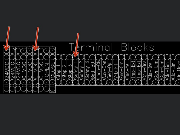
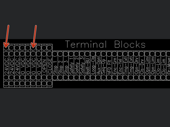
Using the Free Ends of the Cables, Wire them into the Terminal Block inside the Goff's Provided Control Panel.
-
The Receiver has (2) LEDs on the Top of the Unit.
-
The Transmitter has (1) LED on the Top of the Unit.
-
-
-
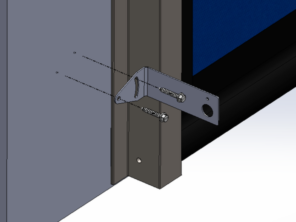
Goff's does not provided fasteners for the mounting surface.
-
The brackets can accommodate up to 1/4in material appropriate faseners.
-
Goff's recommends the sensors be mounted between 6-10in from the floor for pedestrian traffic, and 8-12in for forklift traffic.
-
Keep the brackets a few inches away from the side guides.
-
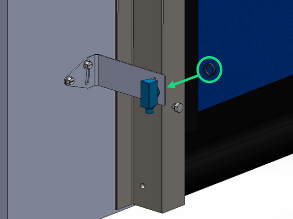
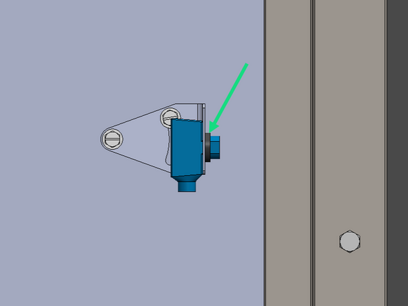
Once the brackets are mounted on the wall, thread the plastic nuts directly onto the sensors to secure them to the brackets.
-
Goff's recommends mounting the transmitter on the opposite side of the opening from the control panel, and the receiver on the same side as the control panel.
-
-
-
The Receiver can be Identified by its 2 LEDs on the top of the unit.
-
REMOVE FACTORY JUMPER WIRE BETWEEN 24VDC AND SAFETY 1.
-
Receiver Wiring:
-
Brown Wire - 24VDC
-
Blue Wire - 0VDC
-
Black Wire - SAFETY 1
-
White Wire - NOT USED
-
-
-
The Transmitter can be Identified by its Single LED on the top of the unit.
-
Transmitter Wiring:
-
Brown Wire - 24VDC
-
Blue Wire - 0VDC
-
-
-
Because of the Cyclone's ability to handle pressure and wind, we have added photo-eye blanking to our control panel capabilities.
-
This makes it so that the curtain does not trip the photo-eyes (and reverse the door) during a close stroke while under pressure and/or wind load.
-
-
-
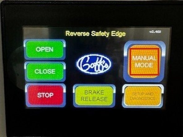
The first step is put the door in Manual mode and jog the door until the bottom edge of the curtain is just above the photo-eyes.
-
From the Operator Screen, Press: SETUP & DIAGNOSTICS > Setup > Settings > Next Screen > Misc Settings.
-
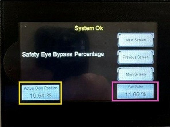
Tap the "Next Screen" button until you see the screen titled "Safety Eye Bypass Percentage".
-
In the lower left corner, you will see the curtains position in which it is just above the photo-eyes (10.64% in this case).
-
Tap in the box in the lower right corner, and set the value to be something just larger than the value in the other box (11.00% in this case).
-
Now your photo-eyes will not be triggered by a bowing curtain.
-
The tradeoff is that if the curtain is down near the photo-eyes even intentionally blocking the photo-eyes will not cause the door to reverse.
-

Team
