-
-
With each Sensor Kit, there will be (2) 15m Cables with Connectors on One End, and Bare Wires on the Other.
-
The Connectors will Screw Directly onto the Sensors.
-
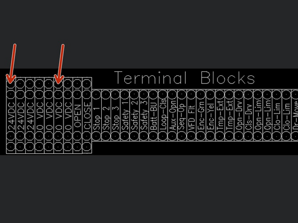
Using the Free Ends of the Cables, Wire them into the Terminal Block inside the Goff's Provided Control Panel.
-
The Receiver has (2) LEDs on the Top of the Unit.
-
The Transmitter has (1) LED on the Top of the Unit.
-
-
-
Use the Provided Fasteners to Mount your SICK Photo-Eye Brackets at the Desired Height.
-
Thread the Plastic Nuts directly onto the Sensors to Secure them to the Brackets.
-
-
-
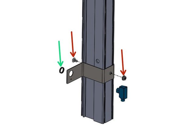
Pre-Drill Clearance Holes for the 1/4-20 Fasteners, at the Desired Sensor Height.
-
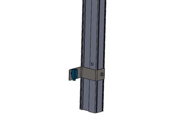
Use the Provided 1/4-20 Screws and Serrated Flange Nuts to Mount your SICK Photo-Eye Brackets using the Holes previously drilled.
-
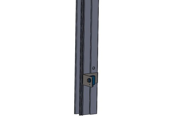
Thread the Plastic Nuts directly onto the Sensors to Secure them to the Brackets.
-
-
-
The Receiver can be Identified by its 2 LEDs on the top of the unit.
-
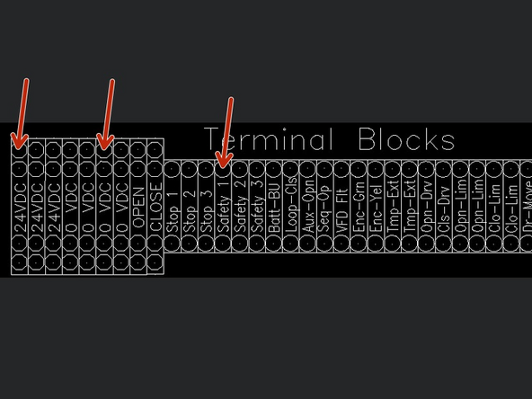
REMOVE FACTORY JUMPER WIRE BETWEEN 24VDC AND SAFETY 1.
-
Receiver Wiring:
-
Brown Wire - 24VDC
-
Blue Wire - 0VDC
-
Black Wire - SAFETY 1
-
White Wire - NOT USED
-
-
-
The Transmitter can be Identified by its Single LED on the top of the unit.
-
Transmitter Wiring:
-
Brown Wire - 24VDC
-
Blue Wire - 0VDC
-
Almost done!
Finish Line


