
Tools
Parts
-
-
Sick Sensor Kits (x2)
-
The RFID Tags will be Mounted to the Vinyl Panel just Above the Bottom Wind Bar upon Receipt
-
Wires, Cables, and Connectors Included
-
Sensor Mounting Brackets (x2)
-
All Necessary Fasteners
-
(2) 6-32 x 3/4" Long Phillips Head Screws
-
(2) 6-32 Nylon Lock Nuts
-
(2) #14 x 1/2" Phillips Head Sheet Metal Screws
-
-
-
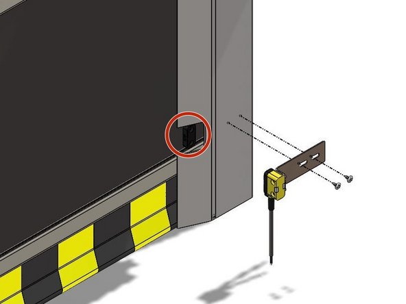
Insert the 6-32 x 3/4" Screws Through the Sensor so that the Screw Heads sit Recessed in the Sensor Housing.
-
See Exploded View
-
Noting the Orientation of the Bracket, Place the Bracket onto the Screws and Secure with the 6-32 Nylon Lock Nuts.
-
-
-
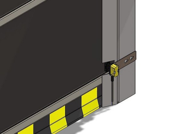
With the Door in the Closed Position, you will see the RFID Tags Mounted to the curtain/bottom-most Wind Bar.
-
Make Sure the Close-Limit is set Appropriately BEFORE Mounting the Sensors.
-
Make a cutout in the vertical track weather seal so that you can see the RFID tag while the door is closed. Make the cutout slightly larger than the RFID tag.
-
Using the #14 x 1/2" Sheet Metal Screws, Mount the Sensor and Bracket Assembly at a Height that Aligns the Sensor with the RFID Tag.
-
It is Best to Drill Small Pilot-Holes First.
-
There are Slots in the Mounting Brackets to allow Adjustment of the Sensors In/Out and Left/Right.
-
-
-
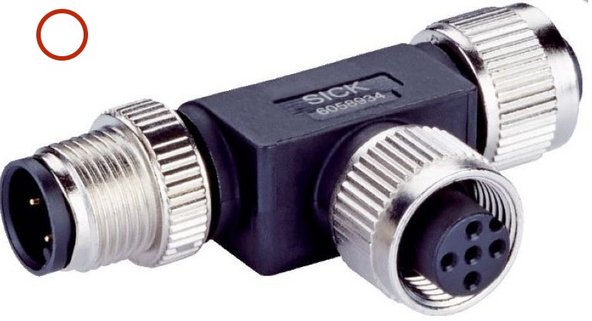
(2) T-Junctions
-
Each T-Junction contains (1) Male 5-Pin Connection, (1) Female 5-Pin Connection, and (1) Female 8-Pin Connection Point.
-
(1) 5-Pin End Connector MLP1-XXT
-
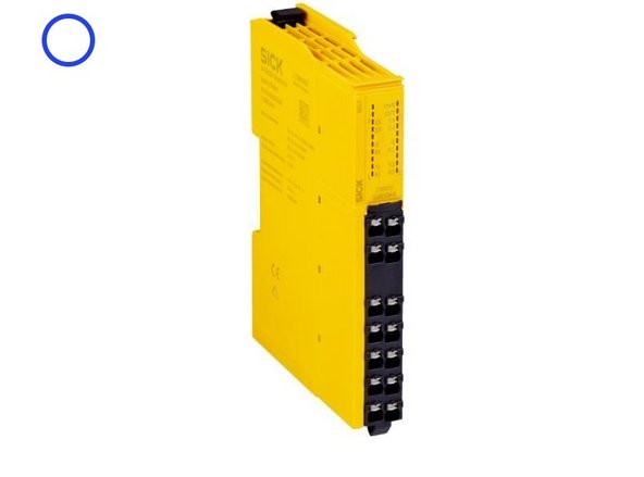
(1) Relay
-
(2) Dual 8-Pin Connector Cables
-
(2) Dual 5-Pin Connector Cables
-
(1) 5-Pin to 4-Wire Cable
-
-
-
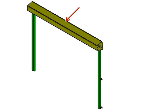
It is Best to Locate T-Junction #1 Somewhere between Sensor 1 and Sensor 2.
-
A Good Spot is above the Header
-
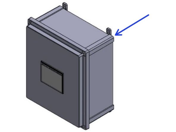
It is Best to Locate T-Junction #2, as well as the Relay, Inside of the Control Panel.
-
Route the Cables Up and Around Using the Door to Secure them Every Few Feet.
-
-
-
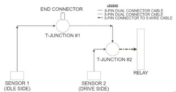
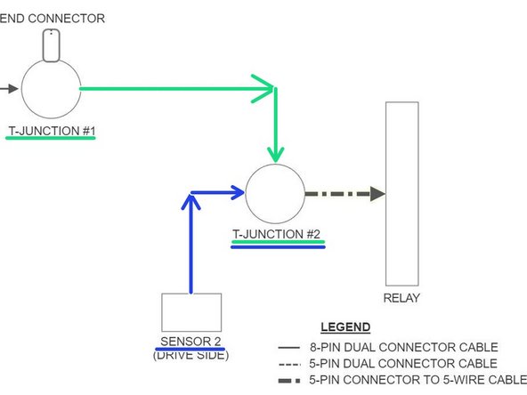
All Connections between Sensors, T-Junctions, and End-Connectors are Screw Connections. There will be only 4 Wired Connections. Two at the Relay, and Two at the Terminal Block within the Goff's Control Panel.
-
See the Basic Layout in Image 1.
-
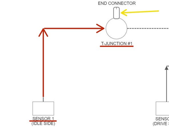
Connect Sensor 1 (Idle Side) to T-Junction #1 with an 8-Pin Dual Connector Cable.
-
Screw the 5-Pin End-Connector onto T-Junction #1.
-
See Image 2.
-
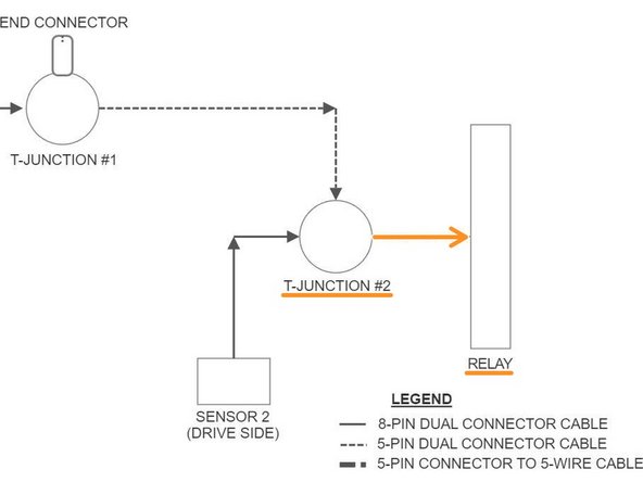
Connect T-Junction #1 to T-Junction #2 with a 5-Pin Dual Connector Cable.
-
Connect Sensor 2 (Drive Side) to T-Junction #2 with a 5-Pin Dual Connector Cable.
-
See Image 3.
-
-
-
Connect T-Junction #2 to the Relay with the 5-Pin to 4-Wire Cable.
-
Screw the 5-Pin Connector onto T-Junction #2.
-
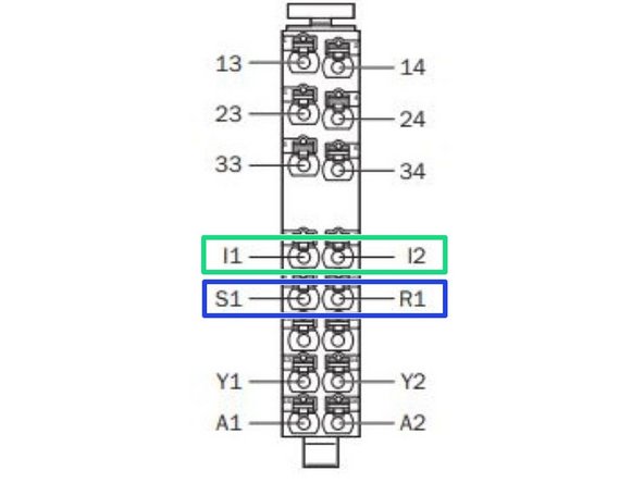
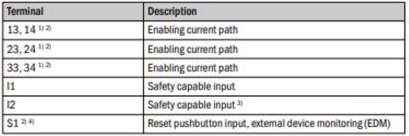
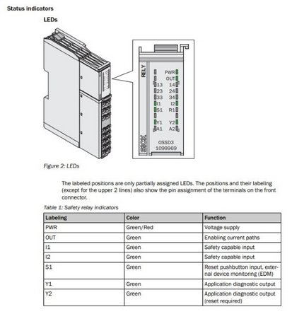
On the Relay, Using the Bare-Wire End of the Cable, Connect the White Wire to I1, and the Black Wire to I2.
-
On the Relay, Put a Jumper Wire between S1 and R1.
-
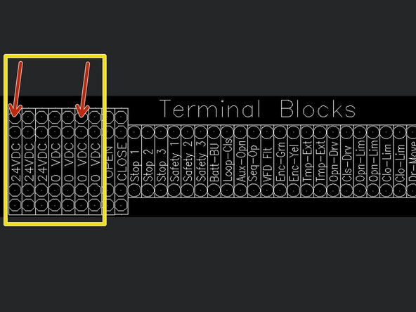
On the Terminal Block Inside your Goff's Control Panel, Connect the Brown Wire to 24VDC, and the Blue Wire to 0VDC.
-
-
-
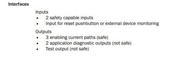
To Integrate Industrial and/or Automation Equipment, Connect to Terminals:
-
13 and 14
-
23 and 24
-
33 and 34
-
These are Safe Circuits, controlled by the Sensors previously Installed, that can Turn Equipment On/Off Based on the Status of the Sensors and their Circuits.
-
For More Information, Please Read the Manuals that are Included with the Sick Sensor Kits.
-


Team
