-
-
BEFORE SWAPPING OUT THE ENCODER ON YOUR GOFF'S DOOR, PLEASE TURN OFF THE AC FEED THAT IS POWERING IT.
-
MAKE SURE THE VFD IS COMPLETELY POWERED DOWN (INSIDE THE CONTROL PANEL) AS THIS ENSURES VOLTAGE/CURRENT IS BEING SENT TO THE MOTOR WINDINGS.
-
The VFD is completely powered down when its Display has no numbers and/or letters displayed on it.
-
-
-
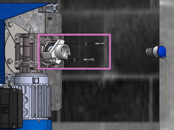
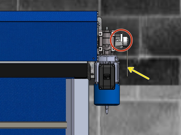
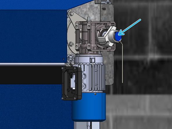
Remove the existing Encoder assembly by removing the (2) M6 Bolts holding it onto the Motor Housing.
-
Make sure to Disconnect the Encoder from the Control Panel before Removing.
-
Remove the Black, Threaded Magnet from the End of the Drive Shaft.
-
Apply Loctite to the threads of the New (provided) Coupling Stud, and Thread it into the Hole in the end of the Drive Shaft.
-
-
-
With the Stud installed on the end of the Drive Shaft:
-
Install the Encoder Mount onto the Motor Housing using the (2) Provided M6 Bolts and Lock Washers.
-
If the Coupler is not already Mounted onto the Encoder Unit, make sure to do that before placing the Encoder inside the Mount. Once inside the Mount, you will not be able to access the Set Screw to secure the Coupler to the Encoder Unit.
-
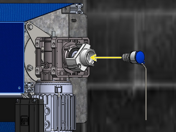
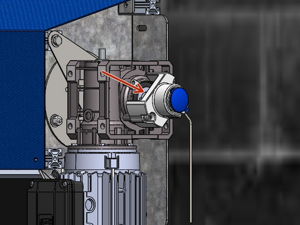
Slide the Encoder Unit + Coupler Assembly into the Mount so that it is fully seated and cannot turn inside the mount.
-
Ensure you also mate the free end of the Coupler onto the Stud on the Drive Shaft.
-
Use the remaining Set Screw on the Coupler to Secure the Encoder Assembly onto the Stud on the Drive Shaft.
-
You may need to manually turn the Coupler to gain access to the Couplers' Set Screw.
-
-
-
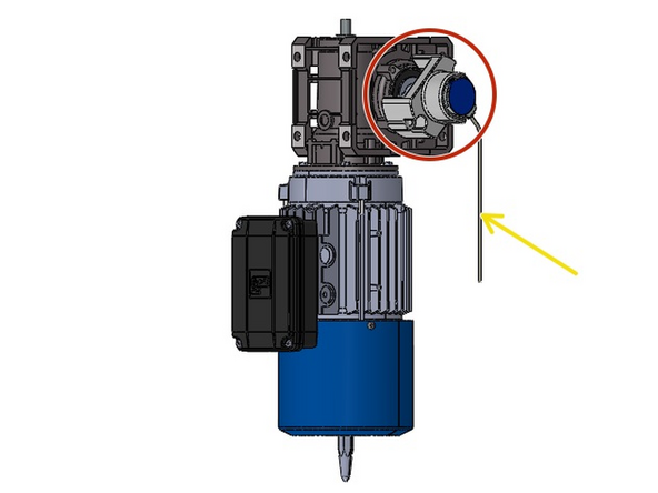
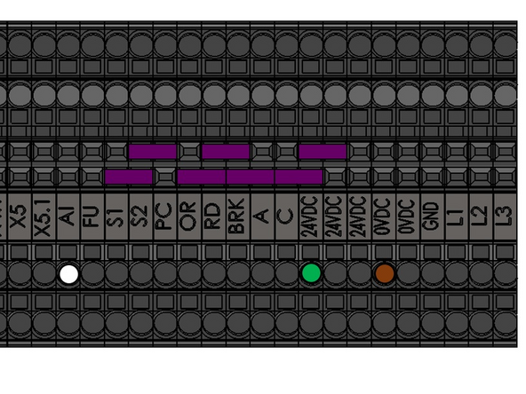
Hanging off of the Encoder, will be a 3-Wire Cable that will need to be Terminated inside the Control Panel.
-
This Cable will be long enough to reach the Control Panel and make the appropriate Electrical Connections.
-
Make the following Encoder Wiring Connections inside the Panel:
-
Green Wire - 24VDC
-
Brown Wire - 0VDC
-
White Wire - AI
-
Excess cable length can be cut off prior to landing its wires, or it can simply be coiled up under or inside the panel.
-
AT THIS POINT, THE MOTOR AND CONTROL PANEL ARE WIRED COMPLETELY. YOU ARE READY TO TURN ON THE POWER, BUT PLEASE BE AWARE OF THE RISK INVOLVED WITH AC POWER, AND TAKE CARE WHEN WORKING ON YOUR GOFF'S DOOR WHILE THE POWER IS ON.
-
-
-
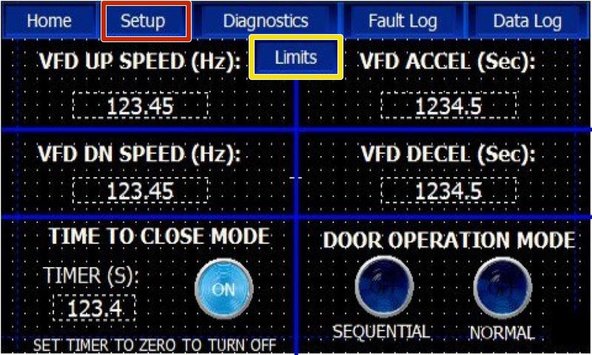
On the Touchscreen, Click the Setup Tab.
-
A new Button will appear labeled "Limits". Click on this Button.
-
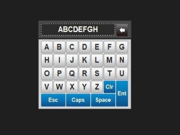
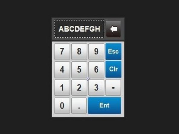
A Keypad will appear in which you must enter the Password: "limits" (all lowercase).
-
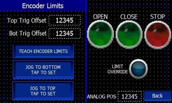
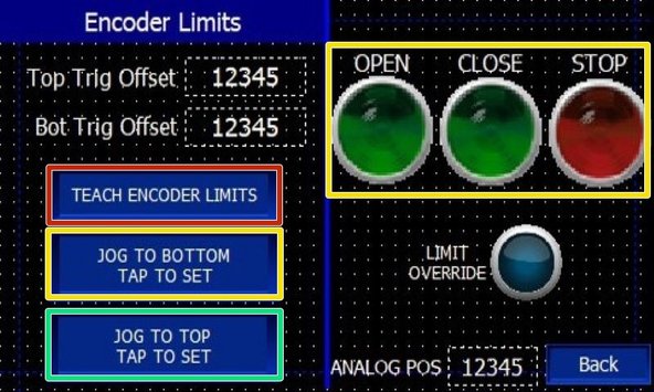
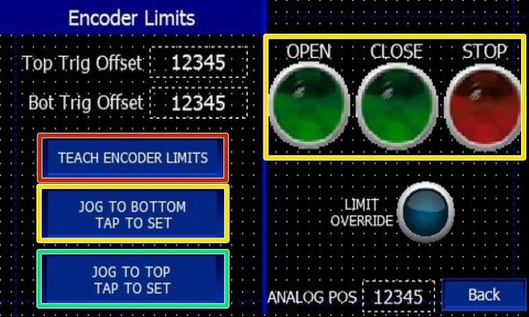
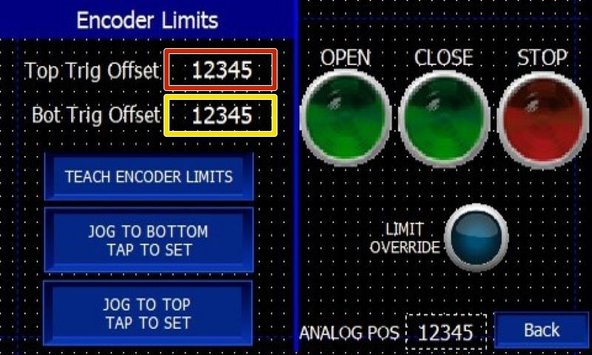
You are now at the Encoder Limit Setup Screen.
-
-
-
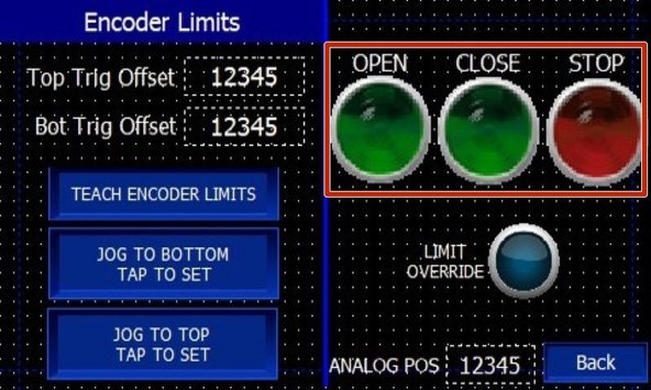
The OPEN and CLOSE Buttons (ON THIS SCREEN ONLY) are Constant Pressure. They will Operate the Door as long as they are Held. Once Released, the Door will Stop.
-
-
-
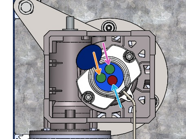
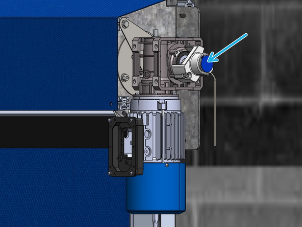
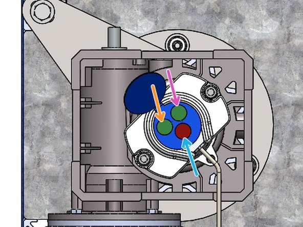
On the Encoder unit flip-open the blue cover, exposing its (3) setting buttons. PRESS THE RED "R" BUTTON TWICE QUICKLY TO ENTER TEACH MODE. The green LED on the encoder will flash and then stay on, indicating that it is in teach mode.
-
On the control panel touch screen, press the "TEACH ENCODER LIMITS" button.
-
Using the CLOSE button on the touch screen, jog the door down by HOLDING the CLOSE button until you have moved the door into the desired closed position.
-
Once at the desired closed position... on the encoder unit, press the green button labeled "0%". The LED on the encoder will flash again and then stay on, indicating that you have saved the closed limit setting.
-
On the touch screen, press the "JOG TO BOTTOM TAP TO SET" button to teach the close limit to the controller. The close limit is now saved in the encoder and taught to the control panel.
-
Jog the door up by HOLDING the OPEN button on the touch screen until the door has reached the desired open position. Go back up to the encoder and press the green button labeled "100%". Again, the LED on the encoder will flash and then stay lit, indicating that it has saved the open limit setting.
-
Back to the touch screen again, press the "JOG TO TOP TAP TO SET" button to teach the open limit to the controller. The open limit is now saved in the encoder and taught to the control panel.
-
Now that both limits are set and taught, go up on the encoder and PRESS THE RED "R" BUTTON TWICE TO EXIT TEACH MODE. The LED will flash and then turn off to indicate that the encoder is out of its teach mode and ready to run.
-
-
-
Test the door's basic operation. You should still be in Limits teaching mode on the touch screen. If you are not still in the Limits teaching mode, get back into that screen using Step 5 from before, and then proceed with the following:
-
Check overall travel by HOLDING the OPEN and then CLOSE buttons until each limit position is reached. If the door reaches each of the taught positions correctly, and you see the ANALOG POS count changing along with door motion, then your limits and encoder are properly set. Close the encoder cover and exit the Limits teaching mode now.
-
IF THE DOOR STOPS SHORT OR IGNORES THE PREVIOUSLY SET LIMIT POINTS, this is an indicator that you will need to reverse the rotation of the encoder's output.
-
NOTE: You will also see that the ANALOG POS count is also not changing or is only jumping from highest to lowest values while your are jogging the door. This too is an indicator that the rotation of the encoder output is incorrect and needs to be reversed.
-
If needed, open the encoder's cover again to expose it's settings buttons. Press the red "R" button quickly twice to put it back into teach mode. The LED will flash and then stay lit to indicate you are in its teach mode again.
-
Now right away...... Press the red "R" button JUST ONE MORE TIME quickly again. The LED will flash to acknowledge you have chosen the reversed rotation.
-
Finish the encoder setup by continuing through the sequences again to teach the door's Closed and then Open limit positions as done previously in Step #7.
-
Finally...... Circle back to testing the operations again. You will now see the ANALOG POS count number running with the door movement and correct limit behavior will be restored.
-
-
-
If the Door is Over-Traveling Past the Taught Open or Closed Limit, Increase the Value of the Corresponding Offset to Make the Door stop Sooner.
-
If the Door is Under-Traveling, and Coming up Short of the Taught Open or Close Limit, Decrease the Value of the Corresponding Offset to Make the Door stop Later.
-
To Adjust the Offsets, Press The Numerical Value in the Corresponding Field, and Adjust as Necessary.
-
Almost done!
Finish Line


