
-
-
The Optex Sensor will be equipped with 8 Wires.
-
The Optex Sensor will be equipped with 8 Wires.
-
White and Brown Wires - Power
-
Green and Yellow Wires - Activation
-
Blue and Pink Wires - Safety
-
Red and Black Wires - Auxiliary/Secondary Output
-
For device setup, adjustments, and additional information, scan the QR code and download the ‘Industrial Door Sensor Setup’ app in the app store. This will allow you to setup and adjust your device from your smart phone.
-
-
-
It is important to note that the Optex sensors should not be used as the primary safety device(s). This means you will be wiring these sensors in addition to a primary safety device (typically through beam photo-eyes).
-
For that reason, we are assuming you are wiring your Optex in as a secondary and/or tertiary safety device.
-
This manual will explain how to wire these devices as such.
-
-
-
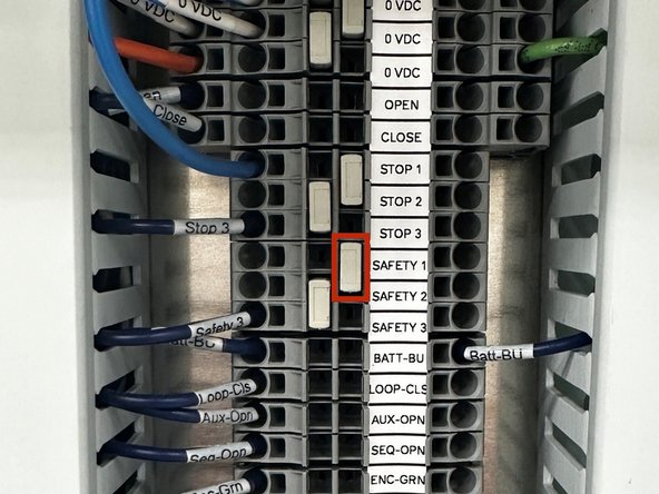
REMOVE FACTORY JUMPER BAR BETWEEN SAFETY 1 AND SAFETY 2.
-
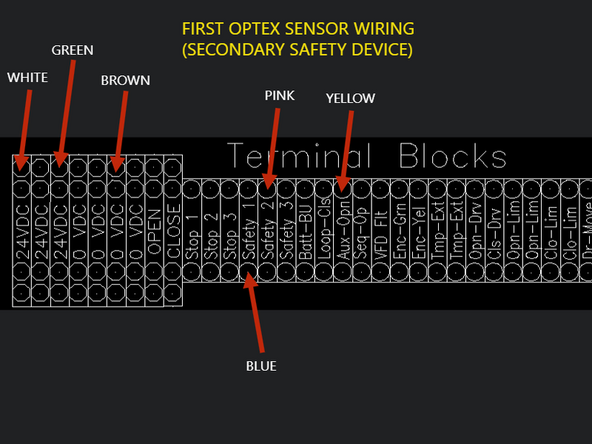
WHITE WIRE - 24VDC
-
GREEN WIRE - 24VDC
-
BROWN - OVDC
-
BLUE WIRE - SAFETY 1
-
PINK WIRE - SAFETY 2
-
YELLOW WIRE - AUX OPEN
-
The Red and Black Wires are auxiliary outputs and are not used for standard setup.
-
-
-
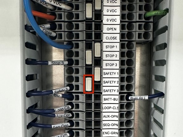
REMOVE FACTORY JUMPER BAR BETWEEN SAFETY 2 AND SAFETY 3.
-
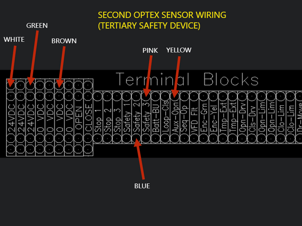
WHITE WIRE - 24VDC
-
GREEN WIRE - 24VDC
-
BROWN - OVDC
-
BLUE WIRE - SAFETY 2
-
PINK WIRE - SAFETY 3
-
YELLOW WIRE - AUX OPEN
-
The Red and Black Wires are auxiliary outputs and are not used for standard setup.
-
-
-
PLEASE NOTE THAT ALL DEVICE SETTINGS ARE CHANGED IN THE APP. NO PARAMETERS, OR SETTINGS CAN BE MANIPULATED ON THE UNIT ITSELF.
-
For additional mechanical and electrical information, as well as troubleshooting information, please see the User’s Guide or Scan the QR Code provided with your device.
-
Additional Setup Reference Links:
-
-
-


Team
