-
-
The Manaras direct-drive Motor comes Pre-Wired from the Factory.
-
In the field, you will need to Wire only the (2) Cables from the Motor into the Control Panel.
-
There is a Motor Cable, and a Limit Cable
-
This is a total of 12 Wires for Single-Phase.
-
And 13 Wires for 3-Phase.
-
-
-
Incoming Power is Terminated in the Lower-Left Corner of the Control Panel.
-
For Single-Phase Power, there will be 3 Wires:
-
Hot (L)
-
Neutral (N)
-
Ground (GND)
-
For 3-Phase Power, there will be 4 Wires:
-
Line 1 (L1), Line 2 (L2), Line 3 (L3), and Ground (GND)
-
-
-
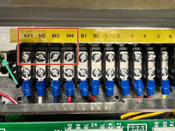
Here is the Color-Coded Wiring Schema:
-
Black to M1
-
White to M2
-
Blue to M3
-
Red to M4
-
Green to Ground Screw
-
-
-
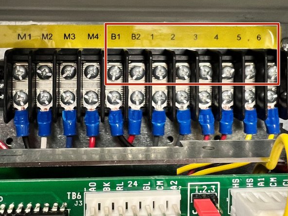
Blue to B1
-
Blue w/ Black Stripe to B2
-
Orange w/ Black Stripe to 1
-
Orange to 2
-
Red to 3
-
Red w/ Black Stripe to 4
-
Black to 5
-
Brown to 6
-
-
-
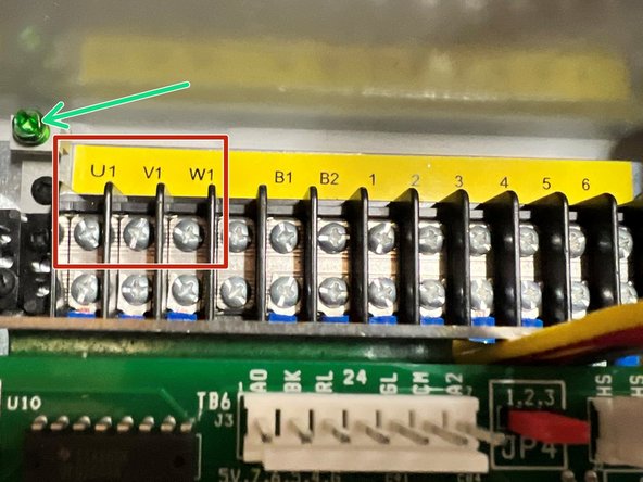
Here is the Color-Coded Wiring Schema:
-
White to U1
-
Red to V1
-
Black to W1
-
Green to Ground Screw
-
-
-
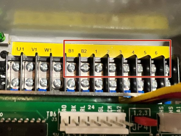
Blue to B1
-
Blue w/ Black Stripe to B2
-
Orange w/ Black Stripe to 1
-
Orange to 2
-
Red to 3
-
Red w/ Black Stripe to 4
-
Black to 5
-
Brown to 6
-
-
-
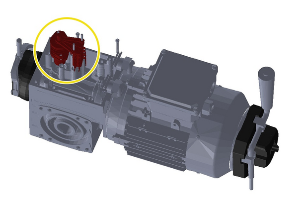
Remove the Black Cover from the Motor to expose the Mechanical-Limit Assembly.
-
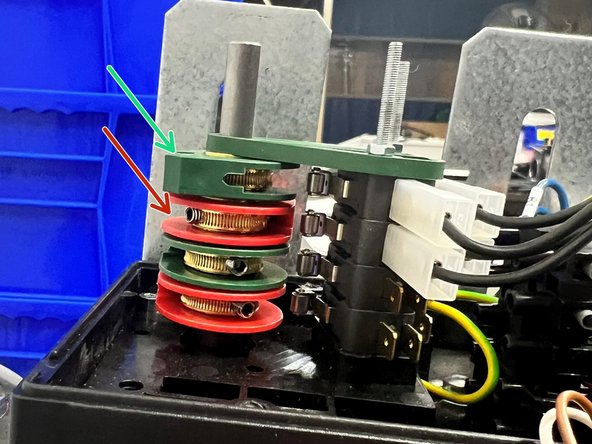
Underneath, there is (2) Green Limit Cams, and (2) Red Limit Cams in Alternating Order.
-
The Top, Green Limit Cam (closest to you) is for the Open-Limit.
-
The Red Limit Cam (just below the Green one) is for the Close-Limit.
-
The (2) remaining Cams are Auxiliary, and could be used for Interlocking, or if you experience a failure in one or both of the Top (2) Limit Cams/Switches.
-
-
-
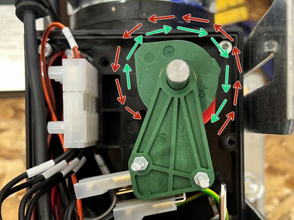
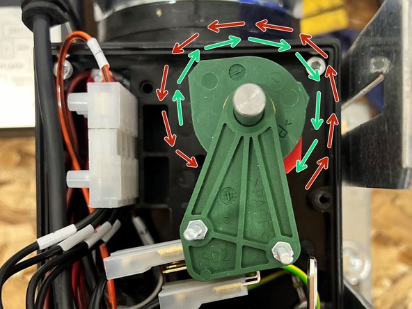
The top, Green (Open) Limit Cam will Rotate Clockwise until it hits the Limit Switch.
-
The Red (Close) Limit Cam will Rotate Counter-Clockwise until it hits the Limit Switch.
-
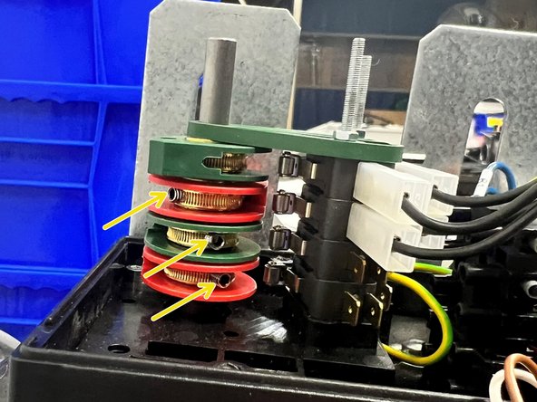
The Limit Cams can be loosened and Adjusted with the Built-in Set Screws.
-
-
-
Run the Door to the desired Closed Position.
-
Loosen the Red Cam's Set Screw, and Rotate the Cam Counter-Clockwise until the Lobe hits the Limit Switch. You will hear an Audible Click.
-
Hold the Cam in this Position, and Tighten the Set Screw to hold it there.
-
Run the Door to the desired Open Position.
-
Loosen the Green Cam's Set Screw, and Rotate the Cam Clockwise until the Lobe hits the Limit Switch. You will hear an Audible Click.
-
Hold the Cam in this Position, and Tighten the Set Screw to hold it there.
-
Test the Limits to confirm accuracy and repeatability. Make any adjustments as necessary.
-
Almost done!
Finish Line


