Tools
-
-
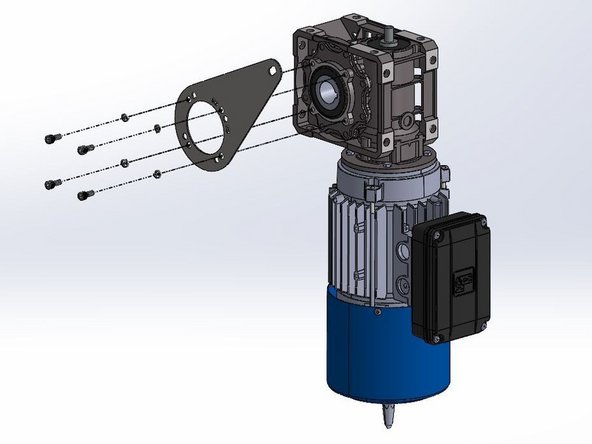
(4) M6 x 10mm Socket Cap Screws
-
Requires 5mm (3/16in) Allen Wrench
-
(4) M6 Split-Lock Washers
-
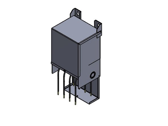
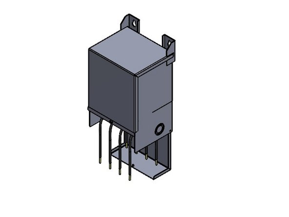
(1) Motor Mount Anti-Torque Bracket
-
-
-
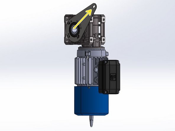
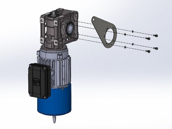
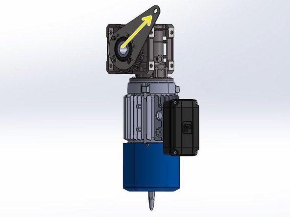
Note the Orientation of the Bracket in Relation to the Motor.
-
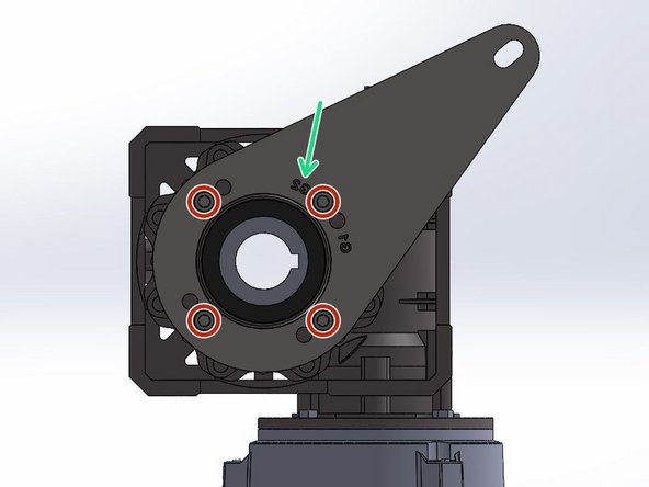
The Bracket has 2 Hole-Patterns Corresponding to G1 and G2 Doors. This ensures the proper Alignment when Installing the Motor Assembly onto a G1 or G2 Door.
-
For a G2 Door, Use the G2 Hole Pattern, and Vice Versa.
-
G1 Doors include Model 2000 and Clean Guard.
-
G2 Doors include Wash Guard, Harsh Guard and Machine Guard.
-
On a LH Drive, G2 Door, the Letters will Read Normally/Forward when the Bracket is Mounted onto the Motor.
-
Place the Bracket up on the Motor with the proper Hole Alignment.
-
Place the Lock Washer onto the Screw and Fasten the Bracket onto the Motor.
-
-
-
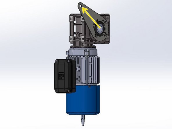
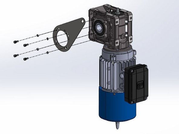
Note the Orientation of the Bracket in Relation to the Motor.
-
The Bracket has 2 Hole-Patterns Corresponding to G1 and G2 Doors. This ensures the proper Alignment when Installing the Motor Assembly onto a G1 or G2 Door.
-
For a G2 Door, Use the G2 Hole Pattern, and Vice Versa.
-
G1 Doors include Model 2000 and Clean Guard.
-
G2 Doors include Wash Guard, Harsh Guard and Machine Guard.
-
On a RH Drive, G2 Door, the Letters will Read Backwards when the Bracket is Mounted onto the Motor.
-
Place the Bracket up on the Motor with the proper Hole Alignment.
-
Place the Lock Washer onto the Screw and Fasten the Bracket onto the Motor.
-
-
-
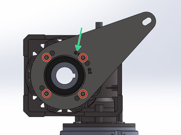
Note the Orientation of the Bracket in Relation to the Motor.
-
The Bracket has 2 Hole-Patterns Corresponding the G1 and G2 Doors. This ensures the proper Alignment when Installing the Motor Assembly onto a G1 or G2 Door.
-
For a G1 Door, Use the G1 Hole Pattern, and Vice Versa.
-
G1 Doors include Model 2000 and Clean Guard.
-
G2 Doors include Wash Guard, Harsh Guard and Machine Guard.
-
On a LH Drive G1 Door, the Letters will Read Backwards when the Bracket is Mounted onto the Motor.
-
Place the Bracket up on the Motor with the proper Hole Alignment.
-
Place the Lock Washer onto the Screw and Fasten the Bracket onto the Motor.
-
-
-
Note the Orientation of the Bracket in Relation to the Motor.
-
The Bracket has 2 Hole-Patterns Corresponding the G1 and G2 Doors. This ensures the proper Alignment when Installing the Motor Assembly onto a G1 or G2 Door.
-
For a G1 Door, Use the G1 Hole Pattern, and Vice Versa.
-
G1 Doors include Model 2000 and Clean Guard.
-
G2 Doors include Wash Guard, Harsh Guard and Machine Guard.
-
On a RH Drive G1 Door, the Letters will Read Normally/Forward when the Bracket is Mounted onto the Motor.
-
Place the Bracket up on the Motor with the proper Hole Alignment.
-
Place the Lock Washer onto the Screw and Fasten the Bracket onto the Motor.
-
-
-
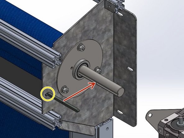
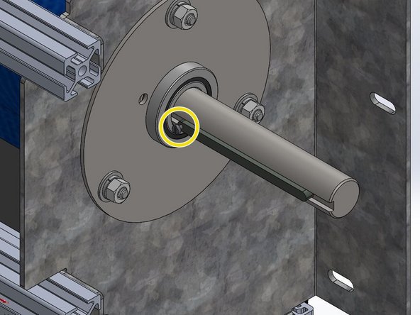
Install the Machine Key onto the Drive Shaft with the Set Screw Oriented Towards the Header (Between Motor and Door).
-
-
-
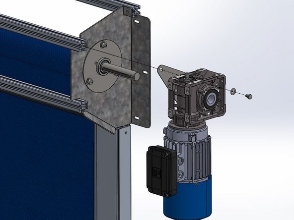
Slide the Motor onto the Shaft and Key.
-
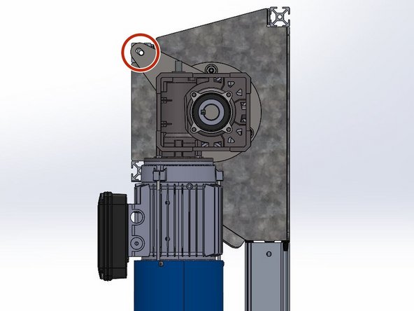
Tilt the Motor to Align the Hole in the Motor Mount Bracket with the Hole on the end of the Upper, Front Rail.
-
This should result in the Motor being oriented Vertically and Plumb (See Image 2).
-
Place the 5/16 Flat Washer onto the 5/16-18 x 1/2in Hex Bolt and Fasten the Motor to the Door with a Ratchet or Impact Driver.
-
If you were provided with a 1/2in Long Black ABS Spacer, Place it Between the End of the Header Rail and the Motor Bracket to Achieve Proper Spacing.
-
-
-
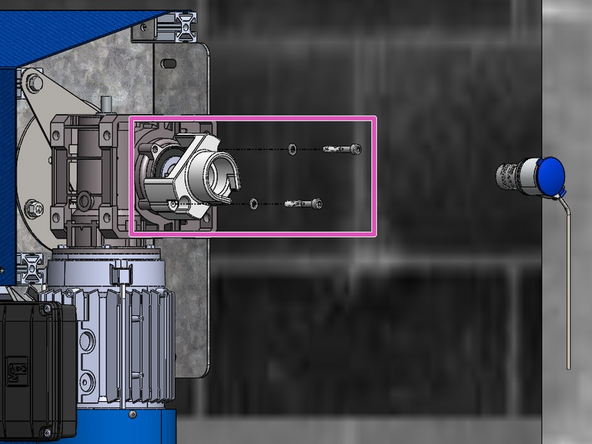
Notice the Stud threaded into the end of the Drive Shaft.
-
Install the Encoder Mount onto the Motor Housing using the (2) Provided M6 Bolts and Lock Washers.
-
If the Coupler is not already Mounted onto the Encoder Unit, make sure to do that before placing the Encoder inside the Mount. Once inside the Mount, you will not be able to access the Set Screw to secure the Coupler to the Encoder Unit.
-
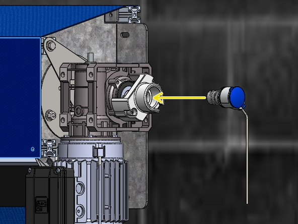
Slide the Encoder Unit + Coupler Assembly into the Mount so that it is fully seated and cannot turn inside the mount.
-
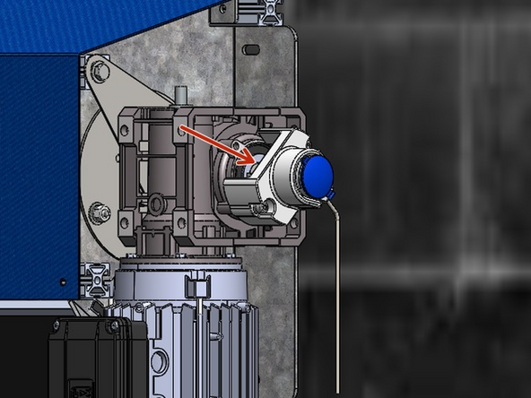
Ensure you also mate the free end of the Coupler onto the Stud on the Drive Shaft.
-
Use the remaining Set Screw on the Coupler to Secure the Encoder Assembly onto the Stud on the Drive Shaft.
-
You may need to manually turn the Coupler to gain access to the Couplers' Set Screw.
-
-
-
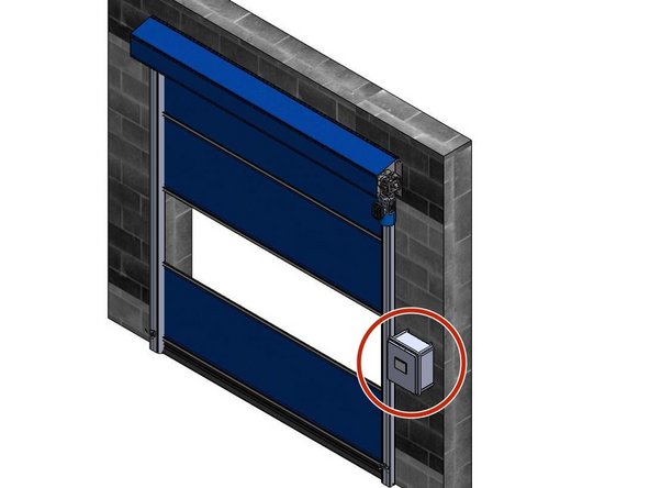
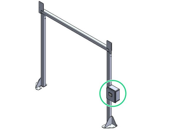
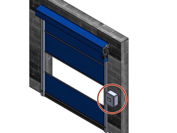
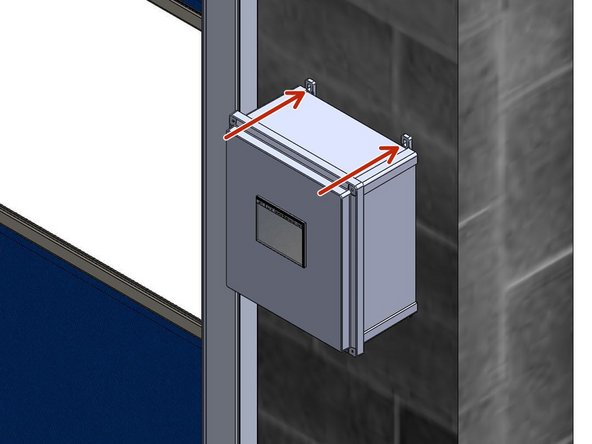
The Goff's Control Panel can be Mounted in two different ways:
-
Flush Mounted on a Wall/Surface with the provided Feet.
-
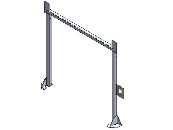
Mounted on a Door Frame with the provided Side-Mount Bracket.
-
Side-Mount Bracket only included when your door is ordered with a Door Frame.
-
-
-
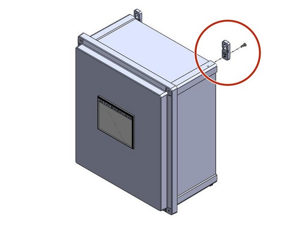
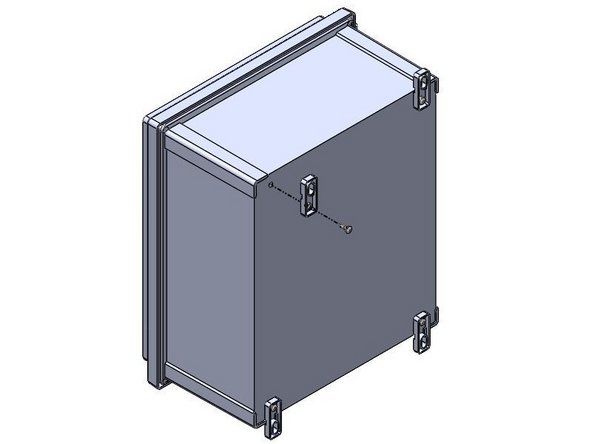
Inside of the Goff's provided Control Panel, there will be a bag containing (4) Feet and (4) 10-32 x 1/2in Screws
-
There are (4) threaded inserts in the back of the Control Panel that will receive the 10-32 x 1/2in Screws.
-
Use these threaded inserts, to Fasten the provided Feet onto the Control Panel.
-
-
-
Goff's does not provide Fasteners for your Mounting Surface. It is up to you to determine the appropriate fasteners for the material you are mounting to.
-
With the appropriate Fasteners, Secure the Control Panel to the wall through the Feet.
-
The Control Panel can be Mounted at any Height or Location as long as the (2) Cables can reach the Motor.
-
-
-
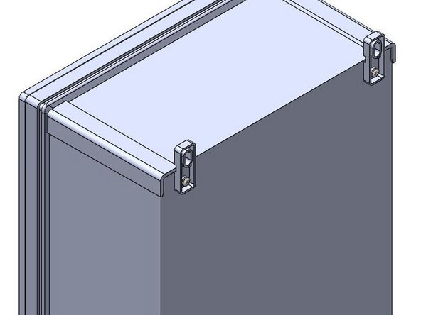
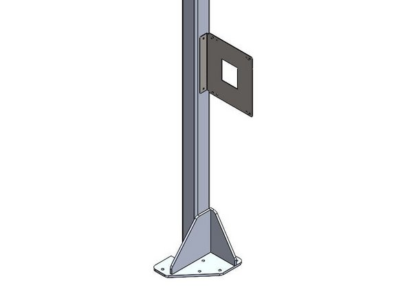
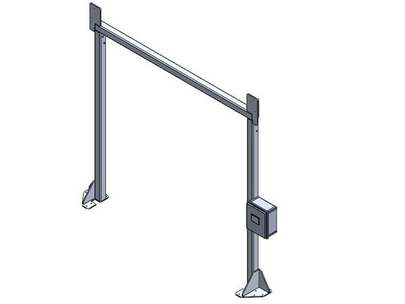
When Side-Mounting a Control Panel onto a Door Frame, the Bracket must be Mounted to the Door Frame Before the Control Panel can be Mounted to the Bracket.
-
Goff's will provide (2) Self-Drilling Fasteners to use for Mounting the Bracket to the Door Frame.
-
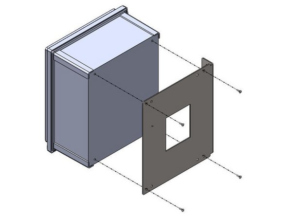
The Bracket/Control Panel can be Mounted at any Location on the Door Frame as long as the (2) Cables can reach the Motor.
-
The Bracket can be Flipped to allow Left- or Right-Hand Mounting.
-
-
-
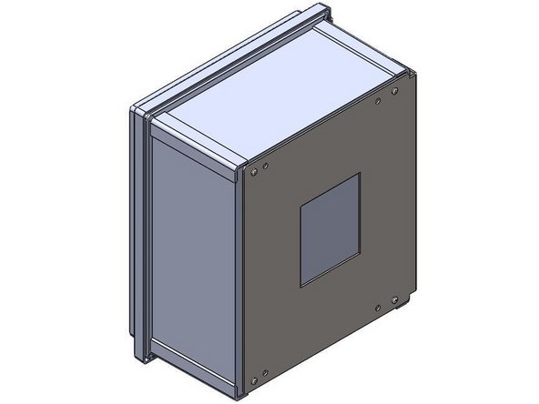
Inside of the Goff's provided Control Panel, there will be a bag containing (4) 10-32 x 1/2in Screws
-
These Screws will be needed to Install Control Panel onto the Side-Mount Bracket.
-
There are (4) threaded inserts in the back of the Control Panel that will receive the 10-32 x 1/2in Screws.
-
Use the Outer-Most Hole Pattern on the Side-Mount Bracket to ensure proper hole alignment with the Control Panel. Use these threaded inserts, to Fasten the Control Panel onto the Side-Mount Bracket.
-
-
-
READ THESE INSTRUCTIONS CAREFULLY. OBSERVE WARNINGS AND PRACTICE CAUTION WHEN INSTALLING, OPERATING, OR MAINTAINING YOUR GOFF’S DOOR ASSEMBLY.
-
WARNING: Damage to the Controller by an un-Certified Electrician will NOT be covered under Goff’s Warranty.
-
DO NOT USE AN IMPACT DRIVER TO MANUALLY OPERATE THE MOTOR AS IT MAY SHEAR OFF THE 13MM OUTPUT SHAFT.
-
BE SURE TO HAVE THE SPECIFIED VOLTAGE COMING INTO THE PANEL. IF THE PANEL IS EXPERIENCING VOLTAGE DROPS OR SPIKES BEYOND WHAT THE PANEL IS DESIGNED FOR, THE PANEL MAY BE DAMAGED OR THE DOOR MAY NOT OPERATE PROPERLY.
-
Regardless of the available Input Power, Goff’s High Performance Doors are supplied with a 3-Phase Motor.
-
The Control Panel will internally “transform” the specified Input Power (from your order) into the appropriate 3-phase Output Power.
-
If only 110V Power is available then a Step-Up transformer will be required.
-
-
-
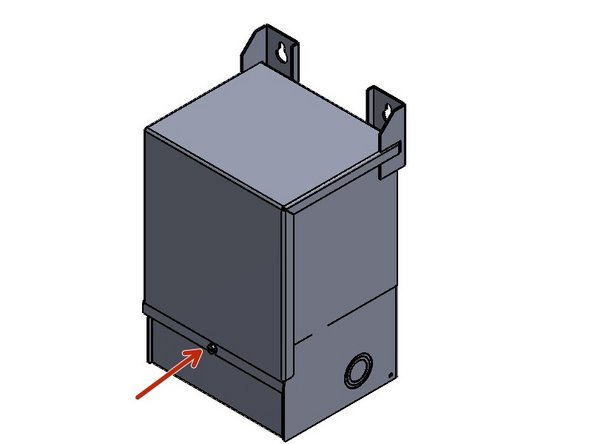
Unpack the Transformer.
-
Check the Information Plate to verify the correct Transformer Input and Output Voltages. "120V to 240V"
-
Mount the Transformer as needed so that Incoming Power can be brought to it, and Outgoing Power can be sent to the Control Panel previously Installed.
-
-
-
Open the Door to access the Wiring Harness.
-
Locate the Wire bundle marked with "X" Conductors.
-
Locate the Wire bundle marked with "H" Conductors.
-
-
-
Make the following Input Connections.
-
H1 - Hot/Line (120VAC)
-
H2 - Fasten together with H4 and Neutral
-
H3 - Fasten together with H1 and Hot/Line
-
H4 - Neutral
-
-
-
Make the following Output Connections.
-
X1 - Hot/Line. Terminates in L1 inside the control panel
-
X2 & X3 - Fasten together
-
X4 - Neutral. Terminates in L2 inside the control panel
-
240VAC is measured between X1 and X4.
-
Make sure Power is OFF while Wiring the Motor to the Control Panel in the following steps.
-
-
-
From the Factory, your Goff's Supplied Control Panel will have (1) Cable coming out of it.
-
This is 6-Conductor "Motor" Control Cable
-
The 6-Conductor Cable has the following colors: Black, Orange, Blue, Red, Green and White
-
-
-
Remove the Cover from the Junction Box on the Face of the Motor.
-
Inside, there will be two Terminal Blocks, both containing the same Markings:
-
On the Top Edge: U1, V1, W1
-
On the Bottom Edge, W2, U2, V2
-
Looking at the Top Terminal Block, you will notice that there are (9) Wires Connected from the Factory.
-
These Factory Connections have been Omitted for Clarity.
-
The Factory Wiring should not need to be Adjusted in the Field.
-
The Bottom Terminal Block will have (2) Wires connected to it from the Factory.
-
-
-
Route the 6-Conductor Bundle from the Control Panel into the Motor Junction Box through the provided Strain Relief.
-
Wire the Motor as Shown:
-
MTR T1 (Black Wire) to W1 (Top Terminal Block)
-
MTR T2 (White Wire) to V1 (Top Terminal Block)
-
MTR T3 (Red Wire) to U1 (Top Terminal Block)
-
Green to Any Junction Box Mount Screw
-
BRK-REL (Blue Wire) to V2 (Bottom Terminal Block)
-
0 VDC (Orange Wire) to U2 (Bottom Terminal Block)
-
-
-
Hanging off of the Encoder, will be a 3-Wire Cable that will need to be Terminated inside the Control Panel.
-
This Cable will be long enough to reach the Control Panel and make the appropriate Electrical Connections.
-
Make the following Encoder Wiring Connections inside the Panel:
-
Green Wire - 24VDC
-
Brown Wire - 0VDC
-
White Wire - AI
-
Once routed into the Control Panel, the unused/excess wire can be Cut off, or Coiled up inside the Panel
-
AT THIS POINT, THE MOTOR AND CONTROL PANEL ARE WIRED COMPLETELY. YOU ARE READY TO TURN ON THE POWER, BUT PLEASE BE AWARE OF THE RISK INVOLVED WITH AC POWER, AND TAKE CARE WHEN WORKING ON YOUR GOFF'S DOOR WHILE THE POWER IS ON.
-
-
-
The "Home" Tab will Include the Primary OPEN, CLOSE, and STOP Buttons.
-
It will also Show the Count-Down Timer Should you Turn on "TIME TO CLOSE MODE".
-
Asterisks will be Replaced with Numerical Value Designating How Much Time (in Seconds) is Left Before the Door Automatically Closes.
-
When "TIME TO CLOSE MODE" is Disabled, the Goff's Logo will Appear.
-
-
-
Press the "Setup" Tab.
-
Notice a New Tab Appears Titled "Limits". Ignore This Tab for now, But This is Where the Limits will be Set Later on.
-
The "Setup" Tab is Where You can Enable/Disable "TIME TO CLOSE MODE", And Toggle Between "SEQUENTIAL" And "NORMAL" Door Operation Modes.
-
Setup Tab is Discussed in Greater Detail in Following Steps.
-
-
-
If you Wish to Setup "TIME TO CLOSE MODE":
-
Navigate to the "Setup" Tab.
-
Press the Numerical Value Field, and Assign the Value Corresponding to the Number of Seconds before you Want the Door to Automatically Close.
-
This Process will Enable "TIME TO CLOSE MODE" And will Assign your Value to the Timer.
-
-
-
To Change the "DOOR OPERATION MODE":
-
Navigate to the "Setup" Tab.
-
Press the Button Corresponding to the Desired Mode of Operation:
-
The Door will come Configured in "NORMAL" Mode, which means the OPEN, CLOSE, and STOP Buttons Function as Their Name Implies.
-
"SEQUENTIAL" Mode makes it so that you can Utilize Single-Button Remotes/Button Stations or Pull-Cords to OPEN, STOP, and CLOSE the Door.
-
"SEQUENTIAL" Mode makes it so that the OPEN Button on the Touch Screen Home Tab Functions as all Commands through the OPEN, STOP, and CLOSE Sequence.
-
The CLOSE and STOP Buttons will still Only CLOSE and/or STOP the Door, Respectively.
-
-
-
To Set the OPEN and CLOSE Limits:
-
Navigate to the "Setup" Tab.
-
Notice a New Tab Appears Titled "Limits".
-
Navigate to the "Limits" Tab.
-
A Keypad Will Appear, at Which Point you Must Enter the Password "limits" (all lowercase) to access the Limit-Setting Screen.
-
-
-
The OPEN and CLOSE Buttons (ON THIS SCREEN ONLY) are Constant Pressure. They will Operate the Door as long as they are Held. Once Released, the Door will Stop.
-
The STOP Button will Stop the Door when it is pressed (Momentary Pressure).
-
-
-
On the Encoder unit flip-open the blue cover, exposing its (3) setting buttons. PRESS THE RED "R" BUTTON TWICE QUICKLY TO ENTER TEACH MODE. The green LED on the encoder will flash and then stay on, indicating that it is in teach mode.
-
Back on the Control Panel Touch Screen, Tap the "TEACH ENCODER LIMITS" Button.
-
Using the CLOSE button on the touch screen, jog the door down by HOLDING the CLOSE button until you have moved the door into the desired closed position.
-
Once at the desired closed position... on the encoder unit, press the green button labeled "0%". The LED on the encoder will flash again and then stay on, indicating that you have saved the closed limit setting.
-
Jog the door up by HOLDING the OPEN button on the touch screen until the door has reached the desired open position. Go back up to the encoder and press the green button labeled "100%". Again, the LED on the encoder will flash and then stay lit, indicating that it has saved the open limit setting.
-
Back to the touch screen again, press the "JOG TO TOP TAP TO SET" button to teach the open limit to the controller. The open limit is now saved in the encoder and taught to the control panel.
-
Now that both limits are set and taught, go up on the encoder and PRESS THE RED "R" BUTTON TWICE TO EXIT TEACH MODE. The LED will flash and then turn off to indicate that the encoder is out of its teach mode and ready to run.
-
-
-
Run a Test Cycle to see Where the Limits Stopping the Door.
-
The Limits May Need to be Re-Taught if they are Significantly Off From Where they Need to be. Repeat the Process in the Previous Step to do so.
-
If the Limits are Off by a Small Margin, you can use the Top and Bottom Offset Settings to Make Minor Adjustments.
-
Think of How the Brakes are Applied in Your Car as You Approach a Stop Sign:
-
The Offsets Represent How Early (or Late) You Begin to Apply the Brakes to Ensure You are Completely Stopped when you Reach the Stop Sign. The Stop Sign is the Limit Position we Previously Taught.
-
-
-
If the Door is Over-Traveling Past the Taught Open or Closed Limit, Increase the Value of the Corresponding Offset to Make the Door Begin to Slow Down Sooner.
-
If the Door is Under-Traveling, and Coming up Short of the Taught Open or Closed Limit, Decrease the Value of the Corresponding Offset to Make the Door Begin to Slow Down Later.
-
To Adjust the Offsets, Press The Numerical Value in the Corresponding Field, and Adjust as Necessary.
-
-
-
The "Diagnostics" Tab
-
Shows, via Indicator Lights, the Status of Each Circuit in the Control Panel. This Tab is Used for Troubleshooting.
-
This Tab also has Built-In OPEN, CLOSE and STOP Buttons.
-
The "Fault Log" Tab
-
Will Record and Display All Faults and Errors that the VFD Encounters.
-
The "Data Log" Tab
-
Shows Total Number of Cycles (Up + Down = 2 Cycle Counts), and Energy Usage in KW-h.
-
One Comment
Trent... This does not show the tapped drive shaft and or the encoder magnet installed either. They should at least be show for reference, and maybe even a quick cutaway showing the nominally correct gap for the encoders too. I know that is all set here at the factory, but we should still show it once assembled and point out the gap range for reference..... just in case someone thinks it's OK for them to be touching or be farther apart than they should be. Thanks!!
Brian Morgan - Resolved on Release Reply


