-
-
(2) Telco Photo Eyes with Threaded, Locking Washers
-
There is a Designated Transmitter marked "SMT".
-
There is a Designated Receiver marked "SMR".
-
(2) G2 Photo Eye Mounting Brackets
-
(4) Self-Tapping Machine Screws
-
Kit will include Double of what is seen in Image above.
-
-
-
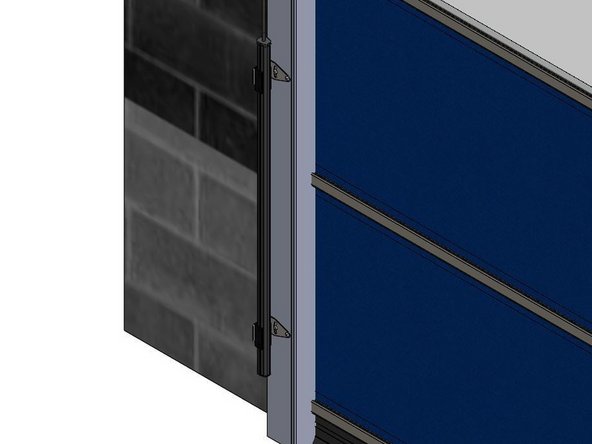
Mark the Desired Height of the Photo-Eyes.
-
Transfer the Mounting Hole Locations onto the Vertical Tracks.
-
Pre-Drill Pilot Holes for the 1/4in Self-Tapping Fasteners.
-
A 7/32in Pilot Hole works well.
-
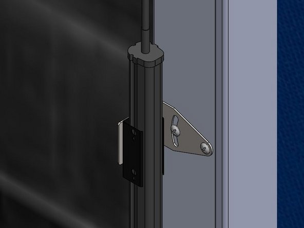
Secure the Bracket to the Vertical Tracks using the 1/4in Self-Tapping Fasteners.
-
Install the Photo-Eyes into the Mounting Brackets with the Threaded Lock Washers.
-
-
-
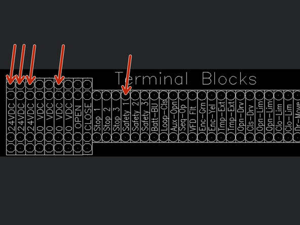
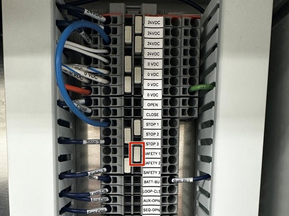
Inside of the Control Panel (on the Main Terminal Block) you will find 2 Factory Jumper Wires.
-
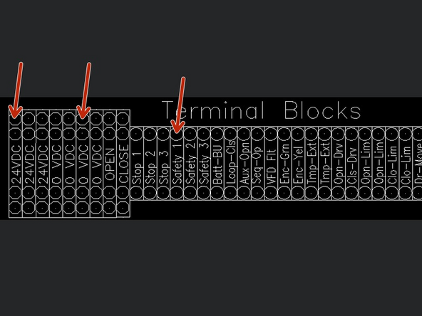
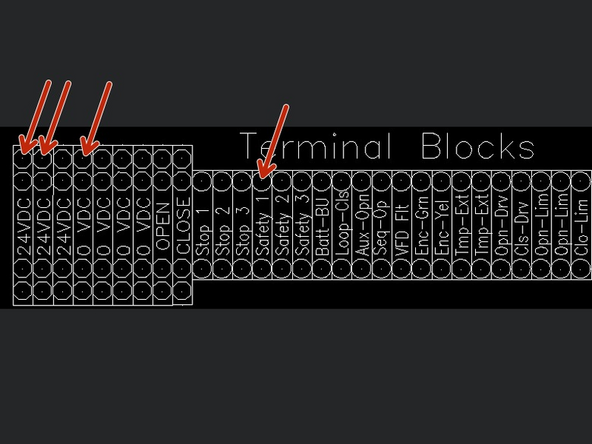
Remove the Factory Jumper that is between Terminals 24VDC and SAFETY1.
-
-
-
The Receiver will be Marked "Receiver" on the device itself.
-
Receiver Wiring:
-
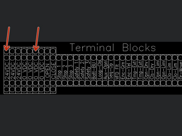
Brown Wire - 24VDC
-
Gray Wire - 24VDC
-
The Brown and Gray Wires can be twisted together and placed in the same 24VDC terminal
-
Blue Wire - 0VDC
-
White Wire - Safety 1
-
Black Wire - 24VDC
-
-
-
The Transmitter will be Marked "SMT" on the device itself.
-
Transmitter Wiring:
-
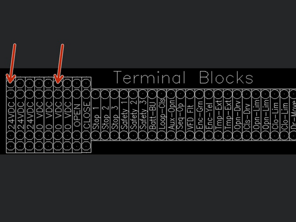
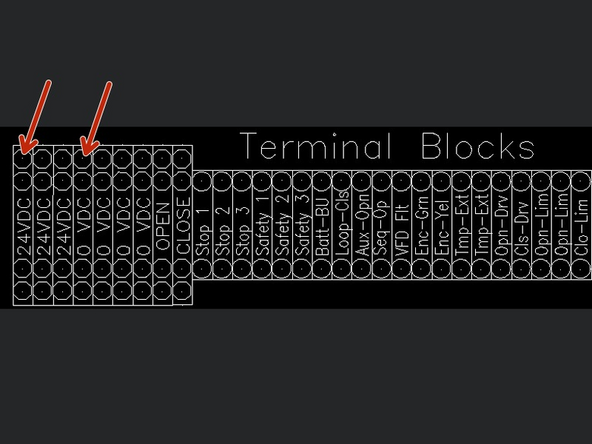
Brown Wire - 24VDC
-
Gray Wire - Not Used
-
Blue Wire - 0VDC
-
Black Wire - Not Used
-
White Wire - Not Used
-
-
-
With each Sensor Kit, there will be (2) 15m Cables with Connectors on One End, and Bare Wires on the Other.
-
The Connectors will Screw Directly onto the Sensors.
-
Using the Free Ends of the Cables, Wire them into the Terminal Block inside the Goff's Provided Control Panel.
-
The Receiver has (2) LEDs on the Top of the Unit.
-
The Transmitter has (1) LED on the Top of the Unit.
-
-
-
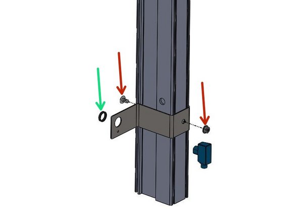
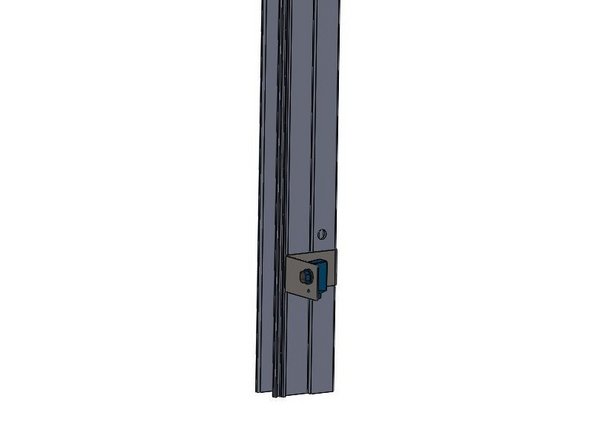
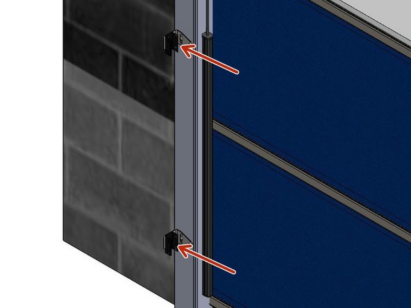
Use the Provided Fasteners to Mount your SICK Photo-Eye Brackets at the Desired Height.
-
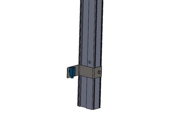
Thread the Plastic Nuts directly onto the Sensors to Secure them to the Brackets.
-
-
-
Pre-Drill Clearance Holes for the 1/4-20 Fasteners, at the Desired Sensor Height.
-
Use the Provided 1/4-20 Screws and Serrated Flange Nuts to Mount your SICK Photo-Eye Brackets using the Holes previously drilled.
-
Thread the Plastic Nuts directly onto the Sensors to Secure them to the Brackets.
-
-
-
The Receiver can be Identified by its 2 LEDs on the top of the unit.
-
REMOVE FACTORY JUMPER WIRE BETWEEN 24VDC AND SAFETY 1.
-
Receiver Wiring:
-
Brown Wire - 24VDC
-
Blue Wire - 0VDC
-
Black Wire - SAFETY 1
-
White Wire - NOT USED
-
-
-
The Transmitter can be Identified by its Single LED on the top of the unit.
-
Transmitter Wiring:
-
Brown Wire - 24VDC
-
Blue Wire - 0VDC
-
-
-
(2) Miller Edge Light Curtains
-
The Light Curtains will each come with (2) Black, Metal Adapter Brackets to Adapt the Light Curtains onto the G2 Light Curtain Track Mounting Brackets.
-
There is a Designated Transmitter marked "TX".
-
There is a Designated Receiver marked "RX".
-
(4) G2 Light Curtain Track Mounting Brackets
-
(8) Self-Tapping Machine Screws
-
(4) 3mm-0.50 x 10mm Machine Screws
-
(4) M3-0.50 Nylon Insert Lock Nuts
-
-
-
Mount the Light Curtain Track Mounting Brackets onto the Door Tracks First, Then Mount the Black, Metal Light Curtain Adapter Brackets onto the Light Curtain Track Mounting Brackets.
-
Mark the Desired Height of the Light Curtains, Making Sure they will be at the Same Height on the Left and Right Sides of the Opening.
-
Transfer the Mounting Hole Locations onto the Vertical Tracks.
-
Pre-Drill Pilot Holes for the 1/4in Self-Tapping Fasteners.
-
A 7/32in Pilot Hole works well.
-
Secure the Brackets to the Vertical Tracks using the Provided 1/4in Self-Tapping Fasteners.
-
Install the Black, Metal Light Curtain Adapter Brackets onto the Light Curtain Track Mounting Brackets using the 3mm Machine Screw and the M3 Nylon Insert Lock Nuts.
-
-
-
The Light Curtains Snap into the Adapter Brackets, and are Retained with an Interference Fit.
-
If the Light Curtains are Sliding/Falling Down in the Adapter Brackets, Simply Bend the Mouth of the Adapter Brackets so that they are more Closed, and Provide a Tighter Grip on the Light Curtains.
-
Make Sure that the Sensing Sides of the Light Curtains are Facing Each-Other.
-
-
-
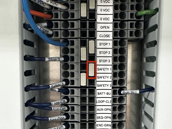
Inside of the Control Panel (on the Main Terminal Block) you will find 2 Factory Jumpers Wires.
-
Remove the Factory Jumper that is between Terminals 24VDC and SAFETY1.
-
With Multiple Safety Devices, they will have to be Wired into the Control Panel in Series.
-
See Step 7.
-
-
-
The Receiver will be Marked "RX".
-
Receiver Wiring:
-
Red Wire - 24VDC
-
Black Wire - 0VDC
-
Orange Wire - SAFETY 1
-
Brown Wire - 24VDC
-
Yellow Wire - NOT USED
-
-
-
The Transmitter will be Marked "TX".
-
Transmitter Wiring:
-
Red Wire - 24VDC
-
Black Wire - 0VDDC
-
-
-
REMOVE FACTORY JUMPER WIRE BETWEEN 24VDC AND SAFETY1 + REMOVE THE GRAY TERMINAL BLOCK JUMPER BAR BETWEEN SAFETY 1 AND SAFETY 2
-
(2) Red Wires - 24VDC
-
(2) Black Wires - 0VDC
-
Brown from Light Curtain #1 - 24VDC
-
Orange from Light Curtain #1 - SAFETY 1
-
Brown from Light Curtain #2 - SAFETY 1
-
Orange from Light Curtain #2 - SAFETY 2
-
-
-
The Optex Sensor will be equipped with 8 Wires.
-
The Optex Sensor will be equipped with 8 Wires.
-
White and Brown Wires - Power
-
Green and Yellow Wires - Activation
-
Blue and Pink Wires - Safety
-
Red and Black Wires - Auxiliary/Secondary Output
-
For device setup, adjustments, and additional information, scan the QR code and download the ‘Industrial Door Sensor Setup’ app in the app store. This will allow you to setup and adjust your device from your smart phone.
-
-
-
It is important to note that the Optex sensors should not be used as the primary safety device(s). This means you will be wiring these sensors in addition to a primary safety device (typically through beam photo-eyes).
-
For that reason, we are assuming you are wiring your Optex in as a secondary and/or tertiary safety device.
-
This manual will explain how to wire these devices as such.
-
-
-
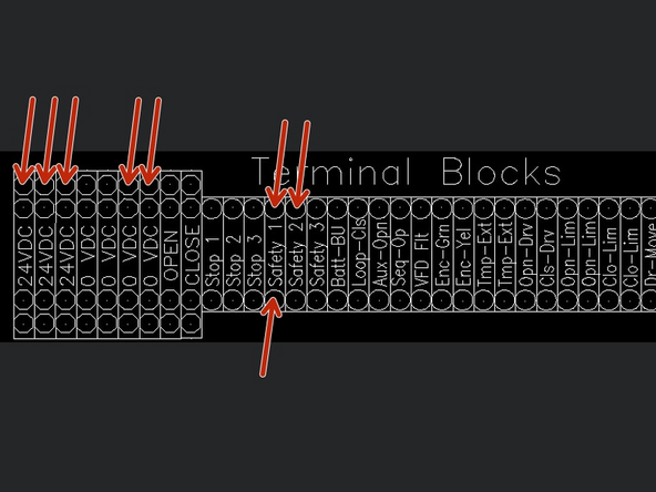
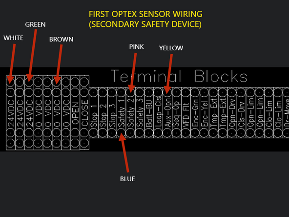
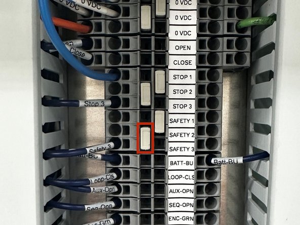
REMOVE FACTORY JUMPER BAR BETWEEN SAFETY 1 AND SAFETY 2.
-
WHITE WIRE - 24VDC
-
GREEN WIRE - 24VDC
-
BROWN - OVDC
-
BLUE WIRE - SAFETY 1
-
PINK WIRE - SAFETY 2
-
YELLOW WIRE - AUX OPEN
-
The Red and Black Wires are auxiliary outputs and are not used for standard setup.
-
-
-
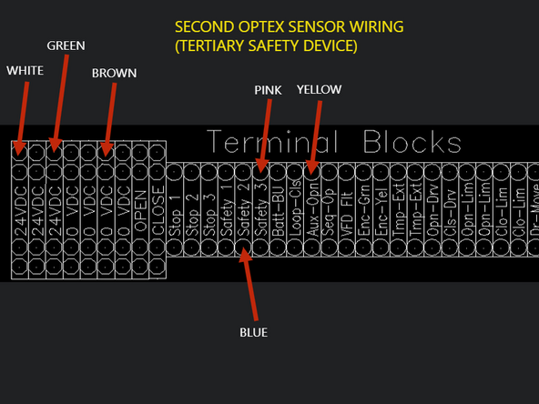
REMOVE FACTORY JUMPER BAR BETWEEN SAFETY 2 AND SAFETY 3.
-
WHITE WIRE - 24VDC
-
GREEN WIRE - 24VDC
-
BROWN - OVDC
-
BLUE WIRE - SAFETY 2
-
PINK WIRE - SAFETY 3
-
YELLOW WIRE - AUX OPEN
-
The Red and Black Wires are auxiliary outputs and are not used for standard setup.
-
-
-
PLEASE NOTE THAT ALL DEVICE SETTINGS ARE CHANGED IN THE APP. NO PARAMETERS, OR SETTINGS CAN BE MANIPULATED ON THE UNIT ITSELF.
-
For additional mechanical and electrical information, as well as troubleshooting information, please see the User’s Guide or Scan the QR Code provided with your device.
-
Additional Setup Reference Links:
-
-
-
-
-
Each LED Strip Assembly comes with pre-installed Pressure Sensitive Hook and Loop Velcro Strips.
-
Peel the Clear Backing off each Velcro Strip (6 Total) and stick the LED Strips onto the Vertical Tracks.
-
The LED Strip with the longer cable (25ft) is mounted on the non-drive side of the opening.
-
Ensure the LED Strip is oriented such that the shortest possible length of Cable is needed to reach the Control Panel.
-
The LED Strip with the shorter cable (10ft) is mounted on the drive side of the opening.
-
Ensure the LED Strip is oriented such that the shortest possible length of Cable is needed to reach the Control Panel.
-
DO NOT LENGTHEN EITHER OF THE LED STRIP CABLES AS THIS MAY CAUSE INCONSISTENT PERFORMANCE. THE PROVIDED CABLE LENGTHS ARE IN THEIR 'WORST-CASE' CONFIGURATION.
-
If the provided Cables do not reach the Control Panel, you will need to re-route them, or add a Junction Box to house the Microcontroller (see next step) in a location where both Cables can reach it.
-
-
-
In your Kit, you will also find the following:
-
One Microcontroller.
-
One Power Supply.
-
5-Condcutor Cable to make the necessary Electrical Connections inside the Control Panel.
-
-
-
Once you have routed the Wires from the LED Strips into the Control Panel, you will have to make a series of Electrical Connections.
-
Find the 5-Conductor Cable provided with the LED Light System.
-
Colors: Green, Blue, Red, Yellow, White
-
-
-
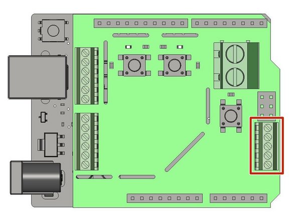
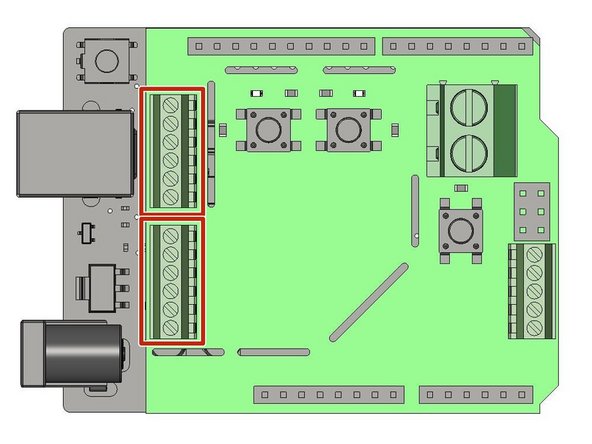
Located the J3 Terminal Block
-
Note the Orientation of the Microcontroller in the Diagram.
-
Make the following Connections on the Microcontroller (from Top to Bottom) using the 5-Conductor Cable:
-
White, Yellow, Red, Blue, Green
-
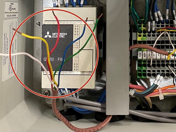
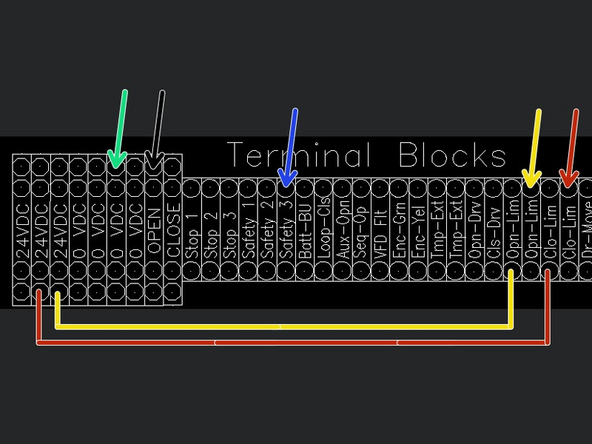
On the other end of the 5-Conductor Cable, the wires Terminate in the Control Panel as seen in Images 2.
-
WHITE WIRE SHOWN AS BLACK ARROW IN IMAGE 2.
-
Multiple Wires can be placed in the same Terminal.
-
(2) Jumper Wires will need to be added in the Control Panel between 24VDC to Opn-Lim, and between 24VDC to Clo-Lim.
-
-
-
Bring the (2) 3-Conductor Cables from the LED Strips into the Control Panel.
-
Locate the J6 and J7 Terminal Blocks
-
Note the Orientation of the Microcontroller in the Diagram.
-
Each Terminal Block receives Wires from One of the LED Strips.
-
Make the following Connections (from Top to Bottom) on each Terminal Block:
-
Red, White, Empty, Empty, Empty, Black
-
-
-
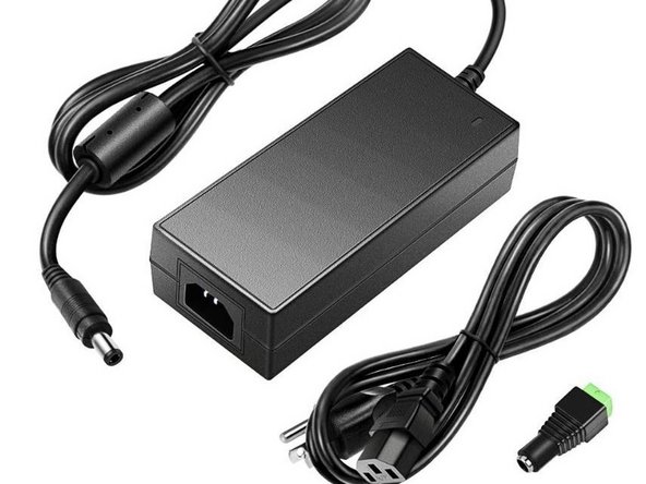
Locate the Provided Power Supply.
-
Bring Power (Single-Phase 120 to 240VAC) to the Power Supply via the Plug or by Hardwiring.
-
Power needs to come from an Outside Source, and should NOT be pulled from the Supply that is feeding your Control Panel.
-
Make sure Electrical Requirements can be fulfilled without straining the System.
-
-
-
Cut the Barrel Connector off of the Output Side of the Power Supply.
-
Bring the Power Supply Output into the Control Panel.
-
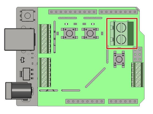
Locate the J9 Terminal Block
-
Note the Orientation of the Microcontroller in the Diagram.
-
Make the following Connections (from Top to Bottom):
-
Red, Black
-
-
-
Before we can Program our LED Door Indicator Light System, we must set up the Time-to-Close (TTC) Feature on our Control Panel.
-
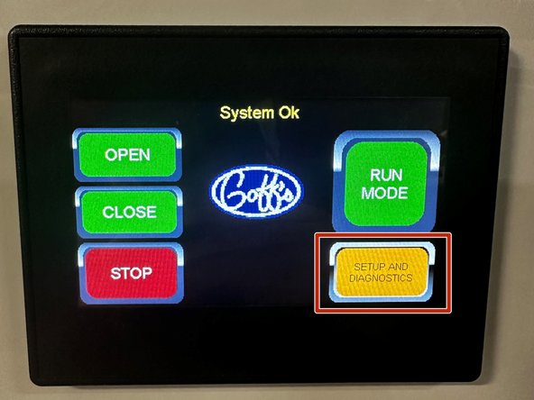
From the Home Screen Press the "SETUP AND DIAGNOSTICS" Button.
-
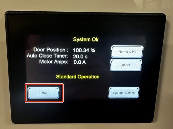
On the Next Screen, Press the "SETUP" Button.
-
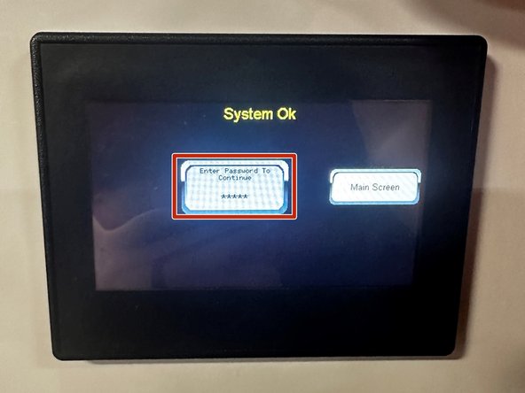
Tap and Enter your Password.
-
Default Password is 123.
-
-
-
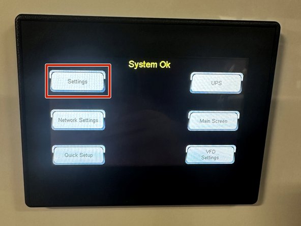
Tap the "SETTINGS" Button.
-
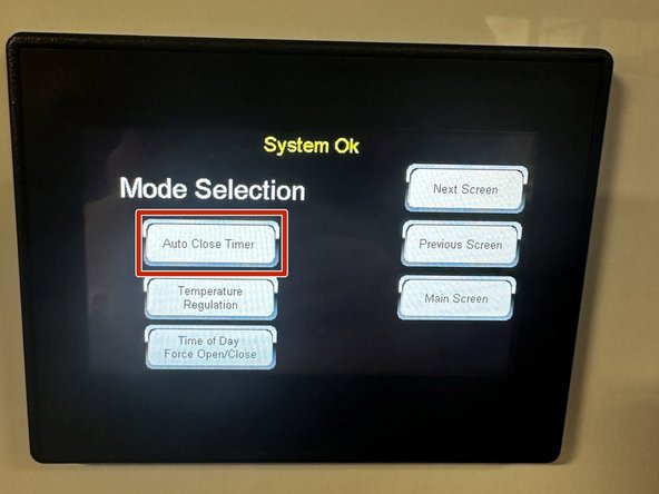
On the Next Screen, Press the "AUTO CLOSE TIMER" Button.
-
-
-
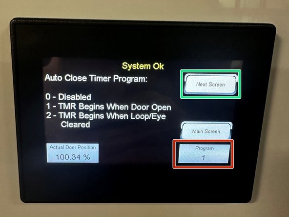
To Enable the Auto Close Timer Program, Tap in the Program box, and Type "1" in the on-screen Keypad. Hit Enter.
-
Tap the "NEXT SCREEN" Button.
-
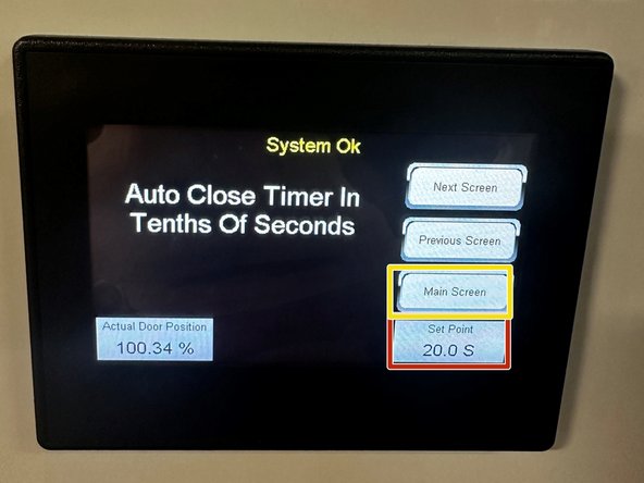
To Set the Auto Close Timer value, Tap in the Set Point box, and in the on-screen Keypad, Type the desired Time (in seconds) before you want the Door to Automatically Close. Hit Enter.
-
Tap the "MAIN SCREEN" Button.
-
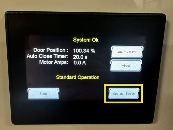
Then Tap the "OPERATOR SCREEN" Button.
-
Your Auto Close Timer is Setup!
-
-
-
From the Operator Screen, Tap the Following Button Sequence:
-
"SETUP AND DIAGNOSTICS"
-
"SETUP"
-
"SETTINGS"
-
"NEXT SCREEN"
-
"N/O AND N/C LIMIT OUTPUTS"
-
Toggle both Limit Outputs to be N/C
-
-
-
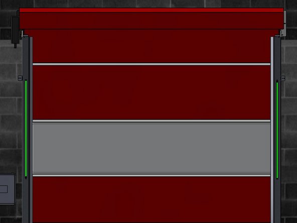
When first Powered On, the LED Strips will Flash Green for One Second. At this Point, Proceed to the
-
If at any point, you need to Restart the Programming Sequence, Press the 'RESET' Button.
-
When the 'RESET' Button is Pressed, the LEDs will Flash Green for One Second. When the Green turns Off, you are ready to Begin the Programming Process.
-
-
-
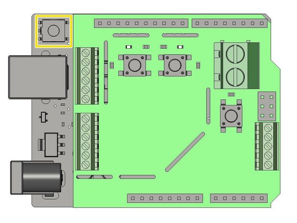
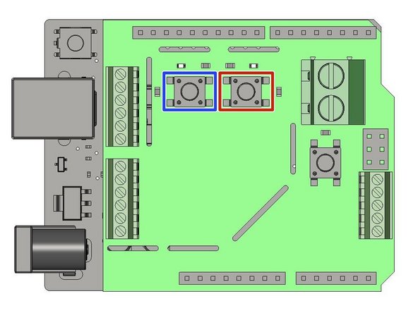
Locate the Blue Button Labeled SW1
-
Each Press of this Button adds One Second to the Timer associated with the LED Light System (10 Presses = 10 Seconds).
-
To Sync the LED Light System with your Control Panel, you must Press SW1 One time for every Second Programmed on your Control Panels' TTC Feature.
-
If your TTC is set for 10 Seconds, you must Press SW1 Ten times.
-
Locate the Blue Button Labeled SW2
-
Once you have Synced your LED Light System with your Control Panel by Pressing SW1, Press the SW2 Button One time.
-
This Locks in your Programming, and Initiates the Light System's Operation.
-
-
-
Your control panel comes with a 24V battery, which can be used during short power outages to release the motor brake if egress is required.
-
This battery will also keep the door travel limits in memory for a short period of time if main power is lost.
-
The battery is not designed to operate the motor, but rather to keep limit settings and release the electrical brake on the motor. Full door functionality should resume when main power is restored.
-
Plug the battery into the 24V port with the proper connector shown below. This connector is pre-wired into your panel from the factory.
-
Turn the battery power switch to the on position.
-
The battery will charge while the main power source is active. When main power is lost the battery will continue to power the low-voltage components in the panel.
-
Almost done!
Finish Line


