Tools
Parts
No parts specified.
-
-
Locate the Main Terminal Block Inside the Control Panel.
-
Locate the Terminals labeled A and C.
-
The Door(s) with wires landed in A and C will be the Inhibiting Door(s).
-
If the Inhibiting Door(s) is/are not fully Closed, the other Door(s) will not be able to be Opened.
-
Place a Wire in Terminal A.
-
This wire will go to Terminal X5.1 on the Inhibited Door.
-
Place a Wire in Terminal C.
-
This wire will go to any Terminal labeled 24VDC on the Inhibited Door.
-
-
-
Locate the Main Terminal Block Inside the Control Panel.
-
Locate the Terminals labeled X5.1 and 24VDC.
-
If the Inhibiting Door(s) is/are not fully Closed, the Inhibited Door(s) will not be able to be Opened.
-
Place a Wire in Terminal X5.1.
-
This wire will go to Terminal A on the Inhibiting Door.
-
Place a Wire in any Terminal labeled 24VDC.
-
This wire will go to Terminal C on the Inhibiting Door.
-
FOR INTERLOCK TO WORK, YOU WILL HAVE TO REMOVE THE FACTORY JUMPER BETWEEN TERMINALS X5.1 AND 24VDC ON THE INHIBITED DOOR(S).
-
-
-
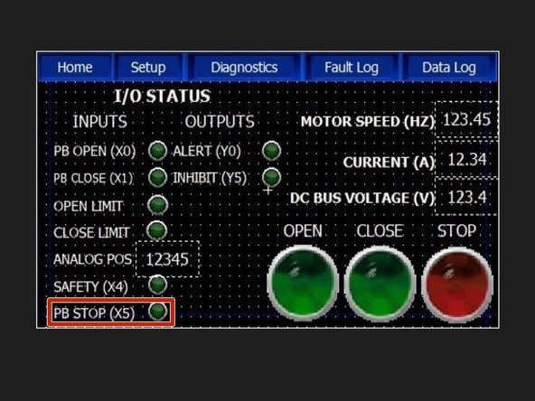
If Wired correctly, when the Inhibiting door is Closed, the PB STOP (X5) LED will be Illuminated on the Inhibited doors, and all Inhibited doors will be free to Operate.
-
When the Inhibiting door is not Closed, the PB STOP (X5) LED will be OFF on the Inhibited doors, and all Inhibited doors will be Inoperable.
-
Basically, the Stop button is being held on the Inhibited door(s) while the Inhibiting door is anything other than fully Closed.
-
INHIBITING DOORS MUST BE CLOSED FOR THE INHIBITED DOORS TO BE OPERATED.
-


