
Introduction
Thank you for ordering a Rigid Frame Shelter integrated with a Weather Wall from Goff’s Enterprises Inc. Please review this guide and follow the steps and tips to ensure proper installation, maximizing the functionality and longevity of your product.
WARNING!!!
READ THIS MANUAL CAREFULLY. INSTALLATION REQUIRES A LADDER AND TWO PEOPLE AT A MINIMUM, OR BY USING A POWERED LIFT. OBSERVE WARNINGS AND PRACTICE CAUTION WHEN INSTALLING, OPERATING, OR MAINTAINING YOUR METAL HOOD. FAILURE TO DO SO COULD RESULT IN SERIOUS INJURY.
Tools
-
-
Technical Support Contacts:
-
Phone: 262-746-3374
-
Email: techsupport@goffscw.com
-
Website: http://www.goffsenterprises.com
-
-
-
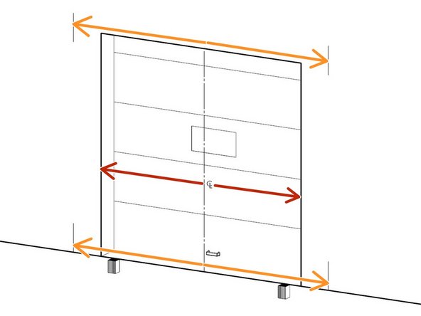
Measure Roof Frame width from outside edge to edge and take note.
-
-
-
Measure the door width and divide that number by 2 to determine the centerline of the door opening.
-
Take the Head Frame width from the previous step and divide that by 2 to determine the Side Pad offset from the door opening centerline.
-
Using the Side Pad offset dimension, mark lines from the centerline of the door opening to each side of the door opening.
-
Make a mark towards the top and bottom of each side of the door opening to help ensure the Side Pads are plumb.
-
These marks will be used in a later step to align the outside edges of the Side Pads.
-
-
-
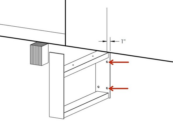
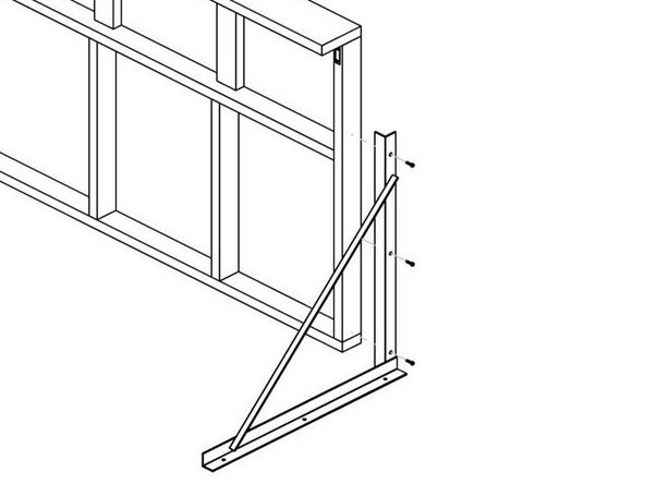
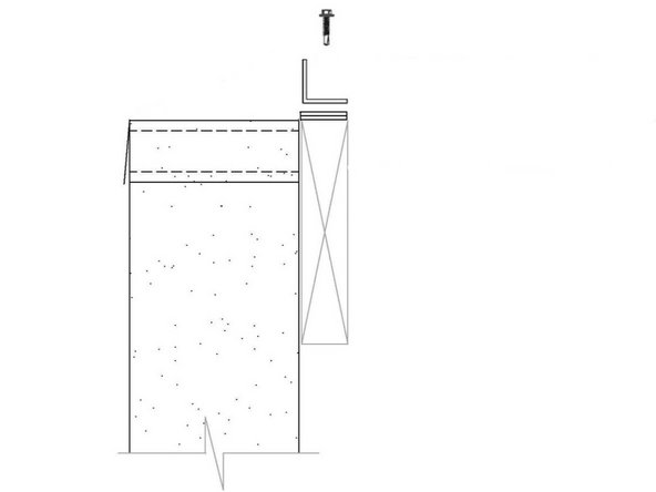
Line up the outside edges of the side frame support mounting plates 1" beyond the marks made in the previous step (further from door opening).
-
The frame mounting plate must be offset 1" from the reference lines so the Side Frames can be centered on the upper C-Chanel of the Frame Supports with the outside faces of the Side Frames aligned with the reference marks.
-
Use a marker to make reference marks in the mounting locations on the wall through the pilot holes on the base frame plate for predrilling.
-
Set the frame aside and predrill concrete anchor holes per installer supplied anchors.
-
Realign Side Frame Supports and anchor to wall surface using concrete anchors or by using other best practices.
-
-
-
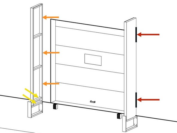
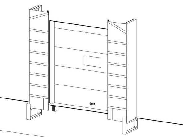
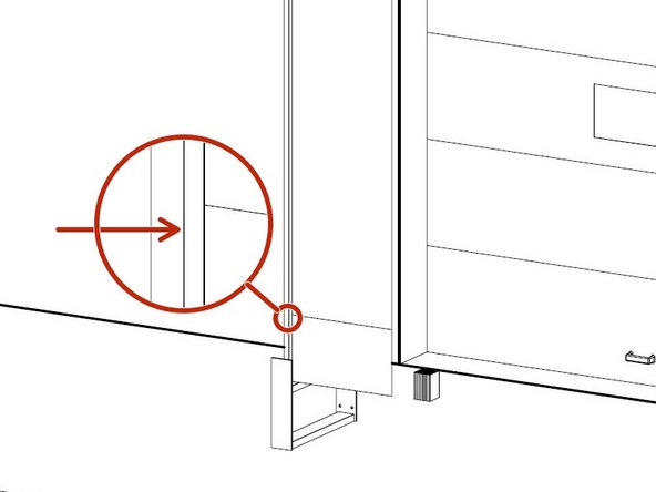
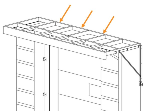
Place the Side Frames onto the Side Frame Support Braces and make sure they are plumb by aligning the outside faces of the Side Frames with the reference lines marked in Step 2.
-
Once Side Frames are plumb and aligned, fasten them to the wall by drilling through the back vertical frame 2x4 between each of the frame braces using at least (3) concrete anchors per Side Frame , or by using other best mounting practices.
-
Be sure to orient the side frames with the end that has (2) closely spaced 2x4 boards on the bottom.
-
-
-
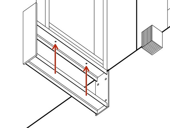
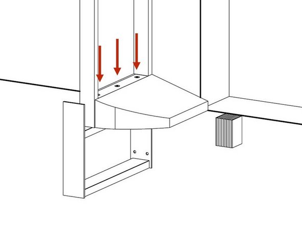
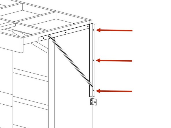
Secure the bottom face of the Side Frames to the Support Braces by using the 1/4"x2" Hex Head Lag Bolts through the pilot holes on the underside of the upper C-Channel.
-
-
-
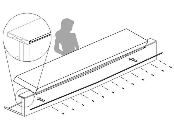
Orient the Draft Pad with the rounded corner facing outwards and the vinyl tab with the (3) grommets on top of the 2x4s inside of the Side Frame.
-
Fasten the vinyl tab into the inside face of the 2x4 bracing on the Side Frames through the (3) grommets using the #14x1-1/2" Phillips Screws.
-
-
-
Using tacks or nails, temporarily pin the left and right face curtains to the Side Frames by fastening through the curtain into the edge of the Side Frames.
-
Be sure the curtains are properly oriented, with the wear pleats on the bottom and the side curtains tapering down towards the center of the door as shown.
-
Fasten the Side Angle Trim to the front left and front right corners of the Dock Shelter using the 1/4" x 1-1/2" Self Drilling Screws.
-
Drill screws along the score line on the Angle Trim adding a fastener 1" from the top and bottom, as well as one into each fiber stiffener (roughly every 14").
-
It is okay to drill a small 1/8" pilot hole into each screw location if you are struggling drilling through all the material.
-
-
-
Head Frame Cover is hidden to show detail.
-
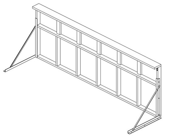
Note that the 2x8 Board is the front of the unit, and the Header Brackets should be flush with the 2x4 Board on the back of the unit.
-
Orient Header Brackets onto the Head Frame as shown.
-
Fasten the Header Brackets to the Head Frame using the supplied Hex Head Screws.
-
-
-
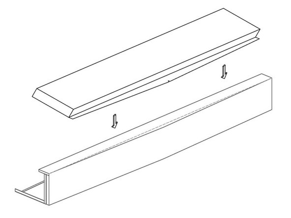
Place the wiper pad on the face plate of the head frame. Center the Pad on the Front 2x8 Board with the top corners of wiper pad flush with top of the Head Frame.
-
-
-
Lay attachment flap down & fasten in place with (3) flat head roofing nails to temporarily secure Wiper Pad.
-
-
-
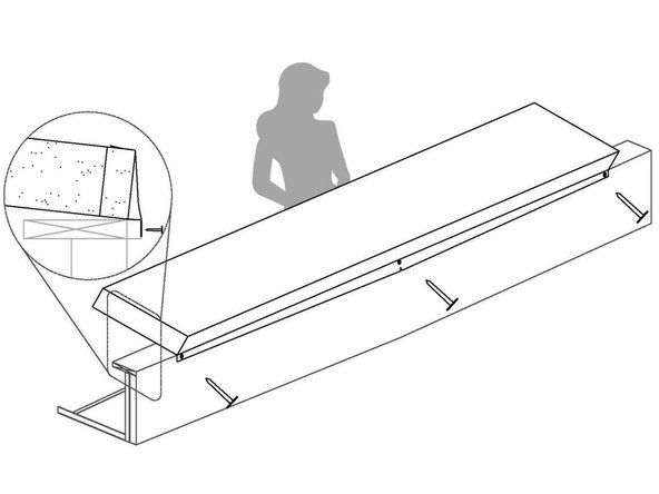
Place Aluminum Angle Trim over Attachment Flap and fasten with provided Hex Head Screws fastening every 11"-12".
-
-
-
Wiper Pad and Head Frame Cover hidden to show detail.
-
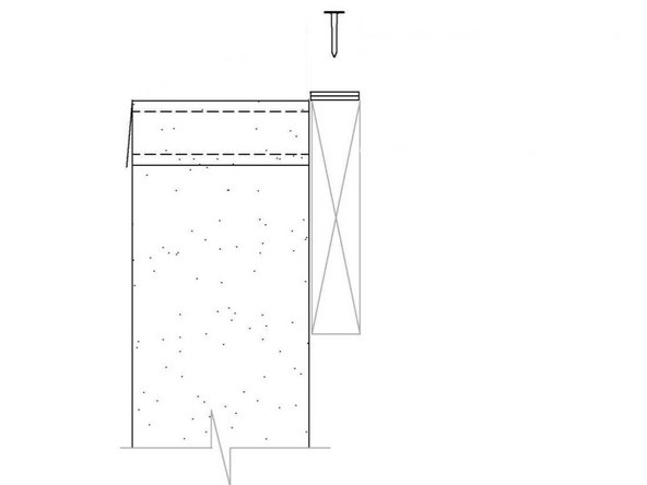
Align the Head Frame Assembly so that The Header Brackets are on the outside of the Side Pads, and Flush against the mounting surface.
-
Anchor Head Frame Supports to the mounting surface using concrete anchors or by using other best practices using the (3) pilot holes in the Bracket.
-
Secure Head Frame to the mounting surface by drilling through the back 2x4 using at least (3) concrete anchors, or by using other best mounting practices.
-
-
-
Side Curtains Hidden in this view to show Bracket location.
-
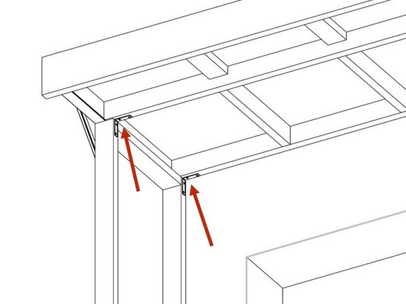
Fasten the 3x3 Angle Brackets in the four upper corners between the Top Frame and the Side Frames using the #8x2" Wood Screws, to ensure the Top Frame is square with the Side Frames.
-
-
-
Wiper Pad and Head Frame Cover hidden to show detail.
-
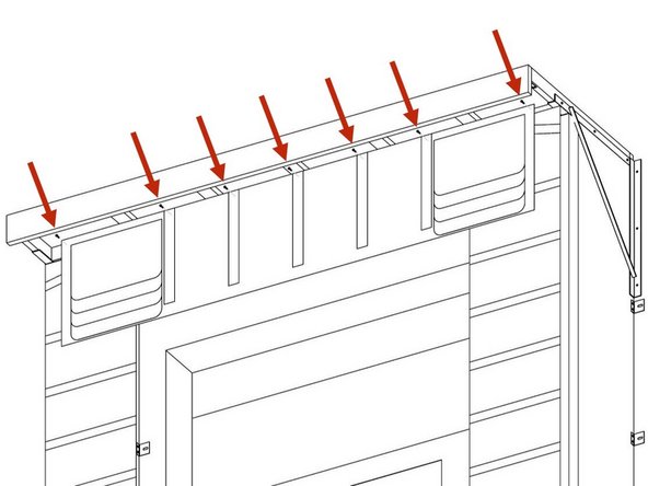
Center The Top Face Curtain and fasten it to the Center Horizontal Beam on The Head Frame all the way butted up to the top of the Cross Beams on The Head Frame using the provided Hex Head Screws.
-
Use a fastener through the top of each Stiffener in the Top Face Curtain and one on each end as shown.
-
-
-
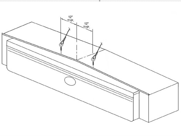
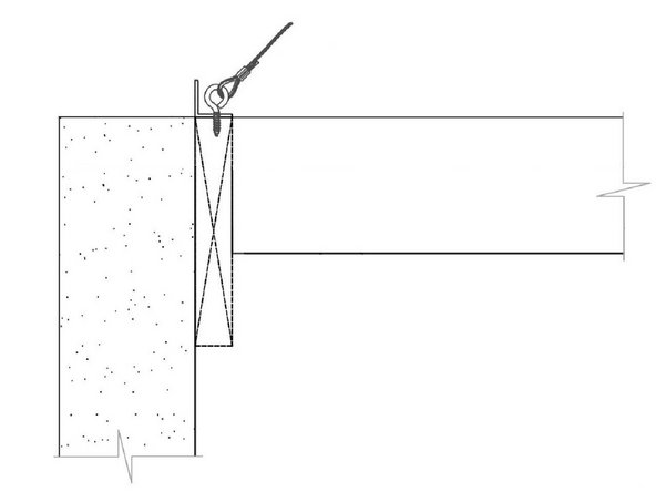
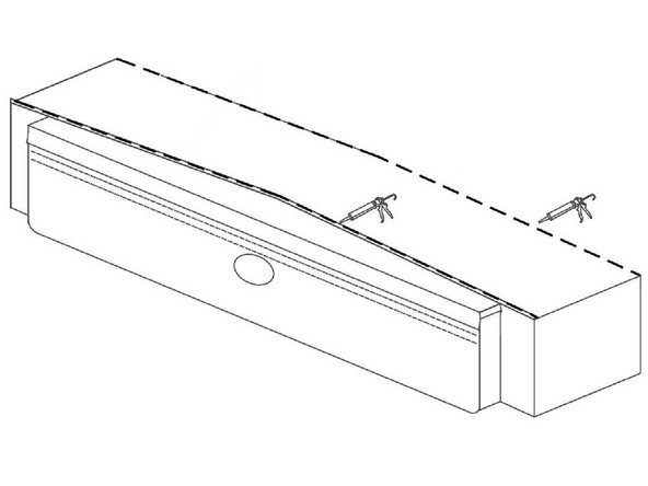
Install two Eye Screws with the Aircraft Cable through the Angle Trim and into the Head Frame 12" off center.
-
Secure the other side of the aircraft cable using best practices for your surface material to anchor the cable to the mounting surface.
-
-
-
Once The Roof Assembly is installed, be sure to caulk anywhere that you can see daylight.
-
Pay extra attention to the gaps between the back edge of The Roof Assembly and the mounting surface.
-
-
-
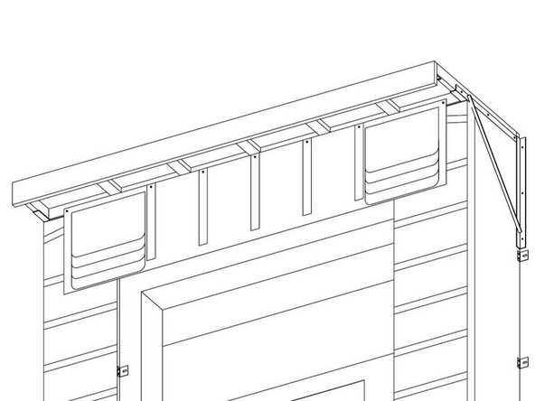
Attach Bungees from the Grommet Tabs in the top of the Left and Right Face Curtains to the Eye Bolts in the Head Frame.
-
Crimp the ends of the bungees to keep them from coming loose.
-


Team
