-
-
Technical Support Contacts:
-
Phone: 262-746-3374
-
Email: techsupport@goffscw.com
-
Website: http://www.goffsenterprises.com
-
-
-
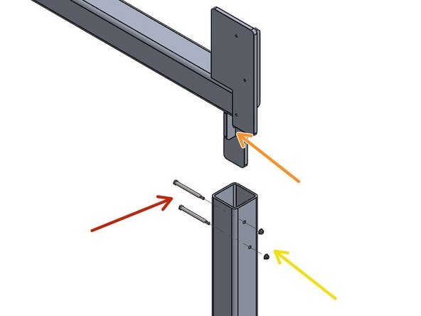
(4) 5/16 Dia. x 4" Long Shoulder Bolts
-
(4) Nylon Lock Nuts
-
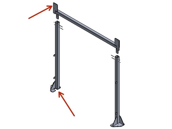
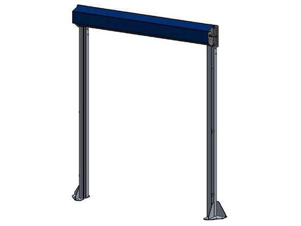
(1) Header Beam
-
(1) Left Vertical Post Assembly
-
(1) Right Vertical Post Assembly
-
-
-
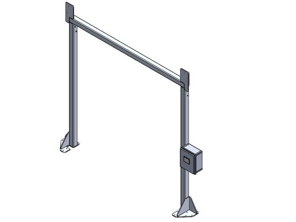
Assembly of the Posts and Beam may be easier laying on the floor.
-
Align the Flanges of the Beam to the notches in the Post Assembly.
-
Insert the Flanges of the Beam into the tops of the Posts.
-
-
-
Insert the 5/16 Dia. x 4" Long Shoulder Bolts from the inside of the Posts.
-
The Upper Bolt should go through the Hole in the Beam Flange.
-
Install the Nylon Lock Nuts on the outside of the Posts.
-
-
-
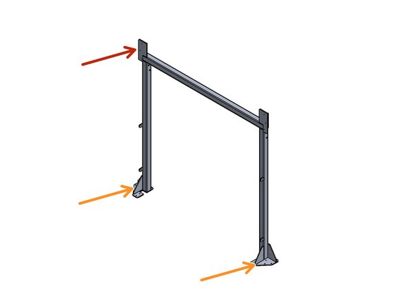
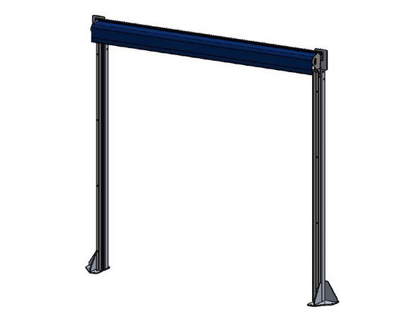
Stand the Post and Beam Assembly upright.
-
Header Mounting Plates will be used to mount the Door Header.
-
Header Mounting Plates should face toward the Door Side.
-
Level and Plumb the assembly, then anchor Base Plates to the floor.
-
-
-
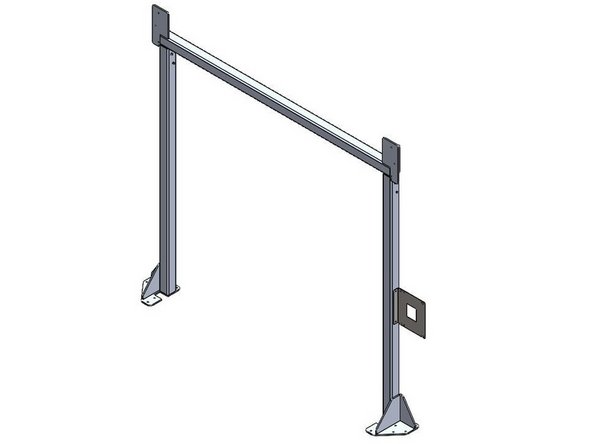
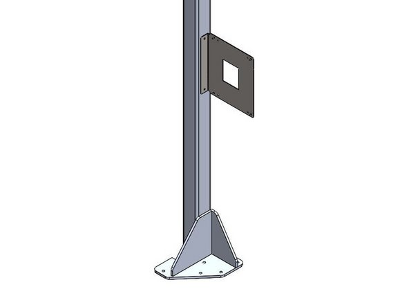
When Side-Mounting a Control Panel onto a Door Frame, the Bracket must be Mounted to the Door Frame Before the Control Panel can be Mounted to the Bracket.
-
Goff's will provide (2) Self-Drilling Fasteners to use for Mounting the Bracket to the Door Frame.
-
The Bracket/Control Panel can be Mounted at any Location on the Door Frame as long as the (2) Cables can reach the Motor.
-
The Bracket can be Flipped to allow Left- or Right-Hand Mounting.
-
-
-
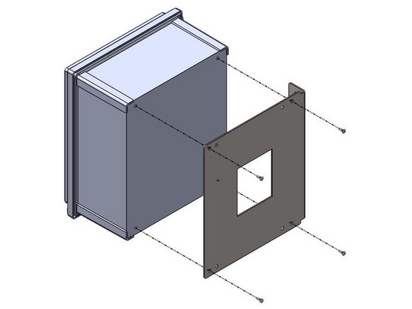
Inside of the Goff's provided Control Panel, there will be a bag containing (4) 10-32 x 1/2in Screws
-
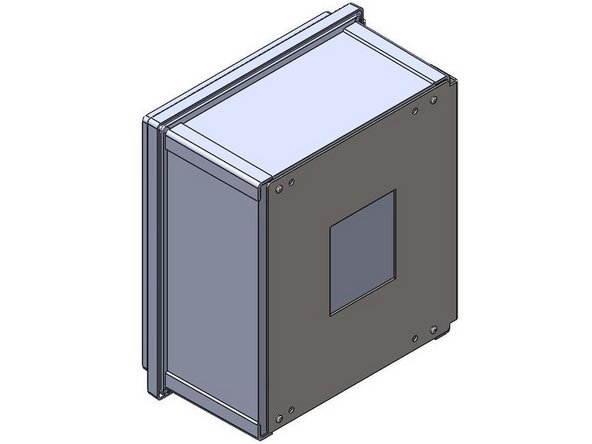
These Screws will be needed to Install Control Panel onto the Side-Mount Bracket.
-
There are (4) threaded inserts in the back of the Control Panel that will receive the 10-32 x 1/2in Screws.
-
Use the Outer-Most Hole Pattern on the Side-Mount Bracket to ensure proper hole alignment with the Control Panel. Use these threaded inserts, to Fasten the Control Panel onto the Side-Mount Bracket.
-
-
-
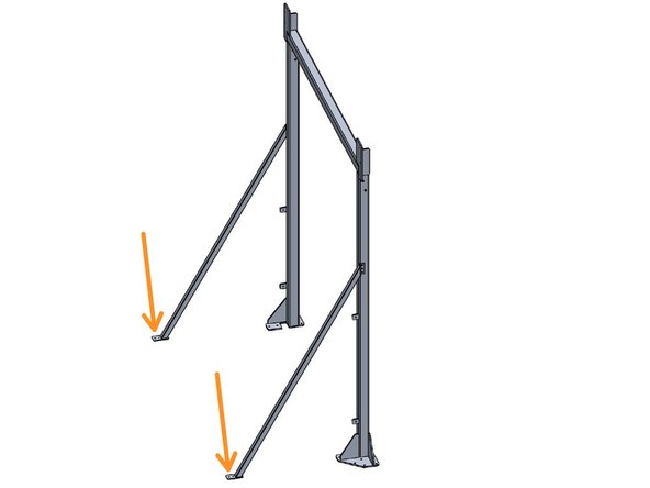
To ensure stability of the Door Frame it is recommended to attach the Braces as shown on Doors over 10' tall. On smaller doors you will not receive these Braces as they will not be needed, and you can skip ahead to the next step.
-
Before securing the Braces to the Door Frame, ensure that the base of the Brace is flush with the floor.
-
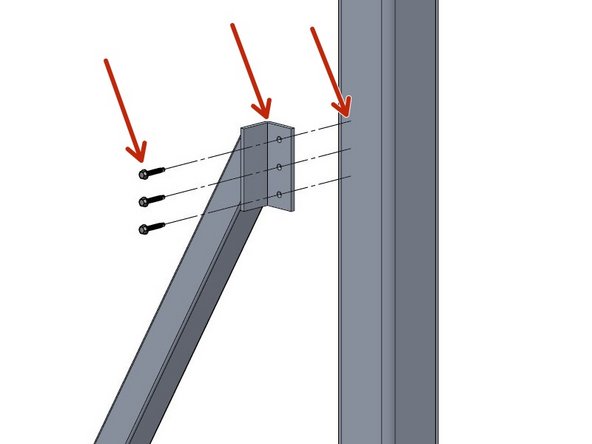
Using the provided 1-1/2" self tapping screws, fasten the Braces by screwing through the pilot holes of the Brace Flange into the outside face of the Vertical Post Assembly
-
Anchor the Braces to the Floor through the pilot holes in the base of the Brace using customer supplied anchors.
-
Repeat for other side.
-
-
-
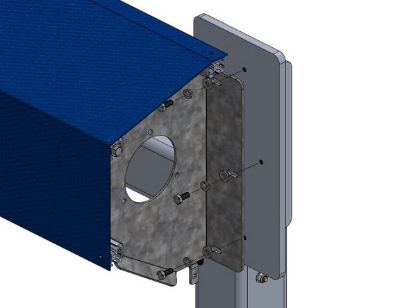
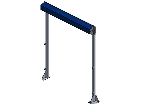
Note: G2 Door Header shown in this step, however, all door styles will mount to the Door Frame in similar fashion. Some hardware and components are hidden to show detail.
-
Align the the Door Header Box with the Door Frame Header Mounting Plates using the slots in the Header Box Flanges to align with the pre-drilled holes in the Door Frame Header Mounting Plates.
-
Loosely fasten the Header Box to the Door frame by taking the provided 5/16-18 x 3/4" Hex Head Bolts through the 5/16" Lock Washer, then through the 5/16" Flat Washer, then through the Header Box Flange Slots, and finally into the Door Frame Header Mounting Plates.
-
Do not fully tighten the bolts until both sides are partially fastened to allow some wiggle room for adjustment of the Header Box on the Door Frame as needed.
-
Once Both sides of the Header Box are mounted in the desired position, fully tighten the bolts to secure the Header Box to the Door Frame.
-
-
-
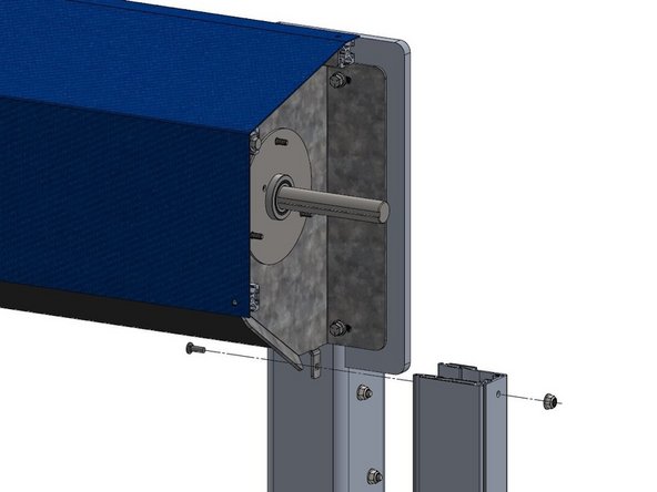
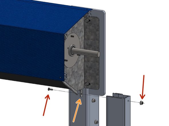
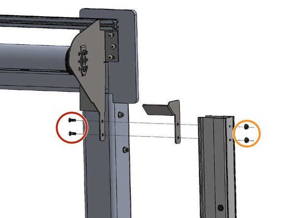
The Track mounts to the Outside of the Tab of the Header Mounting Bracket.
-
It is important to insert the Carriage Bolt from the Inside of the Header Bracket, and to install the Serrated Nut on the outside of the Track.
-
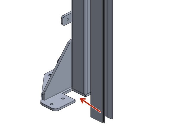
Be Sure the Tracks are inside of the cutout in the Door Frame Base Plates.
-
Depending on the door type you will either Have Aluminum Vertical Tracks or Construction Grade PVC Tracks.
-
See Step 11 for mounting Aluminum Tracks, or Step 12 for mounting Construction Grade PVC Tracks dependent on your track type.
-
-
-
If the door you are mounting has the Construction Grade PVC tracks skip to the next step. This step will cover mounting the door models using the Aluminum Tracks.
-
Using the supplied Carriage Bolt and Serrated Nut, fasten the top of the track To the Header Box Side Bracket.
-
Ensure that the the Bolt goes through the inside tab of the Header Box Side Bracket first and then into the inside of the Vertical Track and tighten the Nut snug.
-
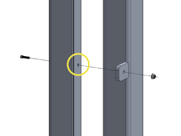
With the Vertical Tracks aligned with the Mounting Tabs on the Vertical Door Frame Post, pre-drill a 9/32" hole into the Vertical Track using the Hole in the Tabs as a pilot hole.
-
Secure the Vertical Tracks to the Door Frame Tabs by using the supplied 1/4-20x 1" Socket Head Cap Screw from the inside of the track where the pre-drilled holes were just made and tighten the nut from the outside of the track.
-
-
-
The Track Assembly Mounts to the Outside of the Header Mounting Bracket, with the Transition Bracket Sandwiched in the Middle.
-
Insert the (2) Carriage Bolts so that they pass through the Holes in the Header Mounting Bracket, Transition Bracket, and Vertical Track Assembly.
-
Then snug the Hex Nut on the Bolt from the outside.
-
-
-
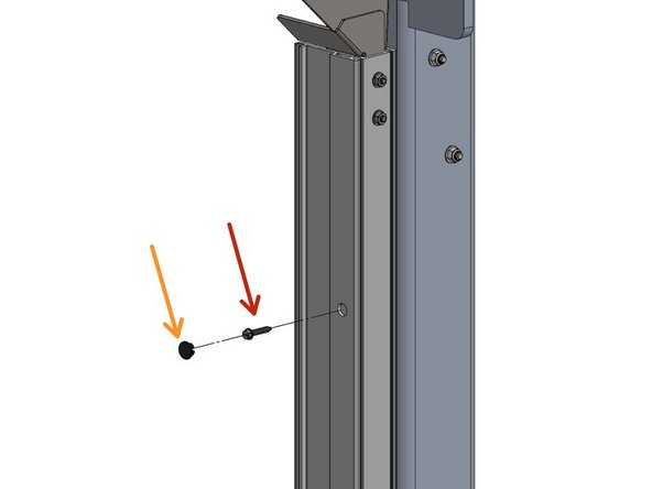
Remove all Black Plastic Plugs from the Track front. These are Mounting access Holes.
-
Use a Level to Plumb the Track or the Door will not operate correctly.
-
Secure the Tracks to the Vertical Post Assembly with Supplied #12 x 1-1/4" Self Drilling Screws with Rubber Washers at each plug location.
-
Replace Plastic Caps.
-
Almost done!
Finish Line


