
-
-
WARNING: Damage to the Controller due to an uncertified Electrician making the connections will not be covered under warranty.
-
Regardless of the available Input Phase and Voltage, you will receive a 3-phase motor.
-
Within the Control Panel, the Input Power is Manipulated to Feed the Motor what is needed.
-
If the only available power is 110V Single-Phase, a Step-Up Transformer is required.
-
The Control Panel received in this instance will be Labeled as 240V.
-
-
-
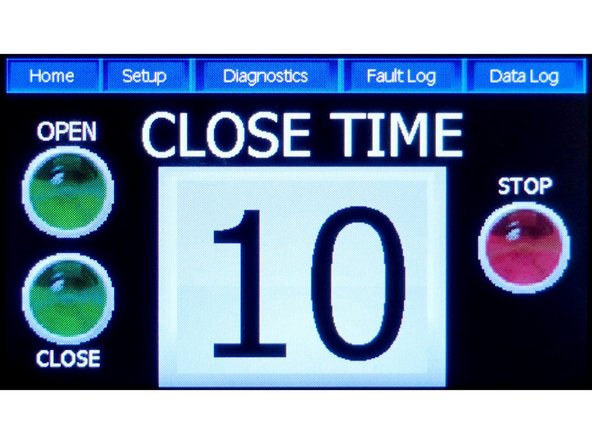
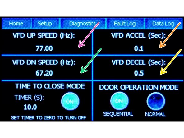
Tabs along the top of the Home Screen. Touch to Open named Screen.
-
Icon Buttons to begin to Open, to Close, or to Stop a moving Door.
-
Close Timer Display (Read Only)
-
-
-
OPEN (Press to Open the door)
-
CLOSE (Press to Close the Door)
-
STOP (Press to Halt the movement of the door while Opening or while Closing)
-
CLOSE TIME (Display counts down the seconds until the Door Close Command is initiated)
-
Interrupting/Breaking the Sensor Beam will reset the Timer to the preset Close Time.
-
-
-
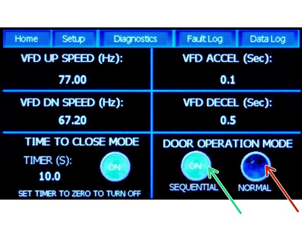
Set to either Normal Mode or to Sequential Mode.
-
For Normal Mode: Press Normal icon, then go to the Home Screen to Open, Close, or Stop. (See Home Screen Instruction above)
-
For Sequential Mode: Press Sequential icon, then use the Push Button Station (single Station), the Single Button Remote, or Pull Cord Switch) to index to the next Mode in order.
-
In Sequential Mode, each switch contact signals an index to the next Sequential Mode in order.
-
Sequential Mode order of index: Open, Stop, Close, Stop
-
-
-
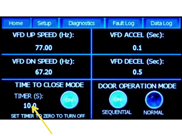
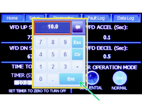
To Adjust the Timer: Press the number (10.0 in picture) below "Timer (s)" text. A Pop-up Keypad is displayed.
-
-
-
Press the desired Timer Delay from the Keypad.
-
Seconds from 0.0 to 60.0 are valid entries.
-
Set the timer to "0" to Turn Off the Auto-Close Timer/Function.
-
Review the display for Timer Close Delay.
-
Press "ENT" to save your Timer Delay.
-
Interrupting/Breaking the Sensor Beam will reset the Timer to the preset Close Time.
-
-
-
VFD Up Speed (Open Door)- given in Hertz (Hz)
-
VFD Down Speed (Close Door) - given in Hertz (Hz)
-
VFD Acceleration - given in Seconds (Sec)
-
VFD Deceleration - given in Seconds (Sec)
-
-
-
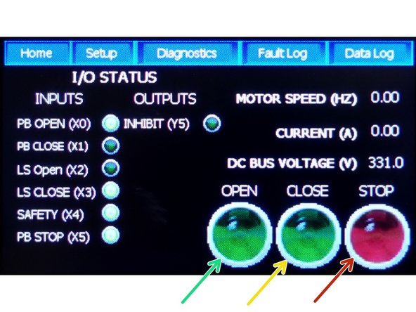
OPEN (Moves the Door up when pressed)
-
CLOSE (Moves the Door Down when pressed)
-
STOP (Halts the movement of the Door when pressed)
-
-
-
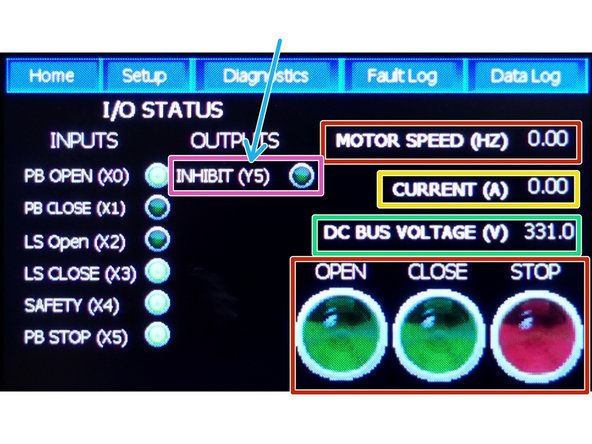
Lights next to the Function (momentarily) indicate the status of that function.
-
Not Illuminated - No Voltage present
-
Illuminated-24VDC Present/ Indicates normal function
-
-
-
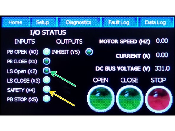
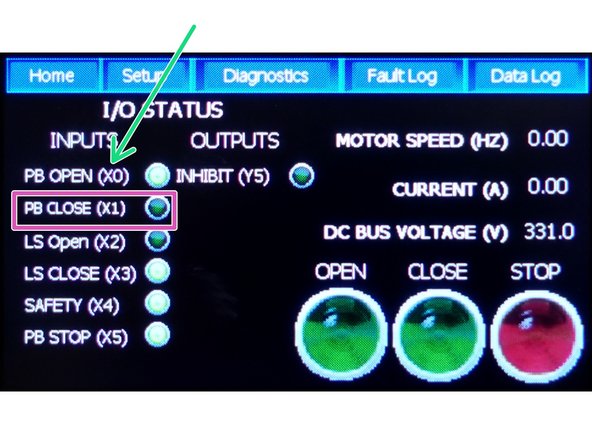
X# refers to the Terminal Block Designation
-
PB OPEN (X0) - Push Button to Open the Door. (Terminal X0)
-
PB CLOSE (X1) - Push Button to Close the Door. (Terminal X1)
-
LS OPEN (X2) The light is the limit switch indicator. When the light is Off it indicates that the Door is Open; When the light is On the Door is not on the Open Switch any longer. Circuit is Normally Closed.
-
LS CLOSE (X3) The light is the limit switch indicator. When the Light is Off the Door is on the Closed/ Limit Switch. Circuit is Normally Closed.
-
SAFETY (X4) Safety Circuit is Normally Closed.
-
PB STOP (X5) (Push Button to Stop the Door’s movement. Reference “X5” in the program) Circuit is Normally Closed.
-
-
-
Y# refers to the Terminal Block Designation
-
Inhibit/Interlock (Y5)
-
MOTOR SPEED - Given in Hertz (Hz)
-
CURRENT - Given in Amps (A)
-
DC Bus Voltage - Given in Volts (V)
-
Functional Open, Close, Stop Icons
-
See Home Screen Instructions for use and function of Open, Close, Stop Commands.
-
-
-
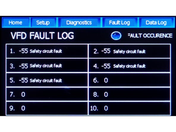
To aid in troubleshooting, problems such as Over Voltage, Short Circuit, Regenerative Power, etc are shown here.
-
-
-
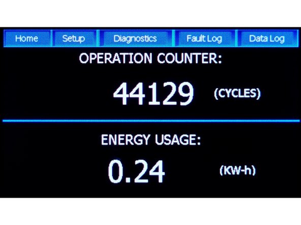
OPERATION COUNTER: XXXXXX (Counts cycles. One Cycle = one complete up movement of the door, and one complete down movement of the door)
-
ENERGY USEAGE X.XX (KW-h) (Given in Kilo-Watts per Hour)
-

Team
