
Introduction
This tubular motor controller is equipped with various features such as sequential mode, manual/auto run-mode selection, N/O vs. N/C configurable safety, and auto-close timer operation. The controller is configurable to suit your needs. Upon startup, you may need to place the relay in “Run” mode by placing a jumper wire between 24VDC and the A/H terminal.
-
-
The sequence of operation is as follows: open, stop, close, stop; repeat. The input is triggered through a 24VDC signal on the “SEQ-OPN” terminal.
-
-
-
The safety circuit can be configured for normally open (N/O) or closed (N/C) input through the press of a button. These terminals are only customizable when the door is in the fully open position, and the open limit is reached. From the main screen:
-
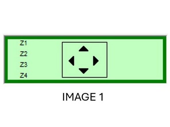
1) Press the “ALT” button located in the top right corner of the smart relay keypad, so the screen changes as shown in Image 1.
-
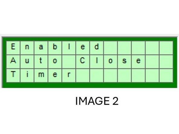
2) Please note: The controller is defaulted to N/C Safety, so to change the controller to N/O Safety, press and hold the “Z2” arrow key for 3 seconds, then press the “ALT” button again. The message in Image 2 will be shown.
-
3) The Safety Terminal is now configured for a N/O input!
-
4) To revert back to the N/C Safety follow the same procedure, but instead of pressing the “Z2” button; press and hold the “Z4” button for 3 seconds, and then press ALT once to exit.
-
-
-
1) Press the “ALT” button located in the top right corner of the smart relay keypad, so the screen changes as shown in Image 1.
-
2) To enable the function, press and hold the “Z1” arrow key for 3 seconds, then press the “ALT” button again. The message in Image 2 will be shown.
-
3) To disable the function, follow the same procedure, but instead of pressing the “Z1” button; press and hold the “Z3” button for 3 seconds and then press "ALT". The previous message will now disappear.
-
-
-
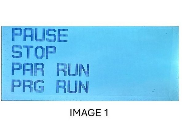
1) From the main screen, press the “ESC” button located in the button left corner of the keypad, so the screen on Image 1 is shown.
-
2) Use the “Z2” button to scroll down to “PAR RUN” then press the “OK” button on the keypad to reach the screen shown on Image 2.
-
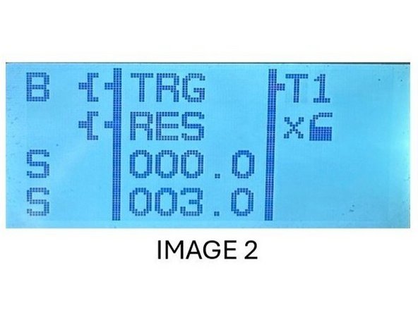
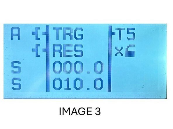
3) Now press the “Z3” button once, so the numerical value of “1” is highlighted with the cursor then press “ALT” to change the number to “5” using the “Z4” button. Once finished press the “ALT” button again to reach the screen shown in Image 3.
-
4) With this screen present press the “Z1” button 3 times until the cursor is on the bottom numerical value (represented by 010.0 in the image above), the auto-close timer setpoint. To change this number press the “ALT” button once to edit the number (use “Z2” and “Z4” to lower or raise the values of each digit).
-
5) Once finished, press the “ALT” button again to the save the number. To exit this menu press the “ESC” button twice.
-
-
-
Record the time it takes your door to complete an open stroke and make note of it for the T11 set point in this step.
-
1) From the main screen, press the “ESC” button located in the button left corner of the keypad, so the screen on Image 1 is shown.
-
2) Use the “Z2” button to scroll down to “PAR RUN” then press the “OK” button on the keypad to reach the screen shown on Image 2.
-
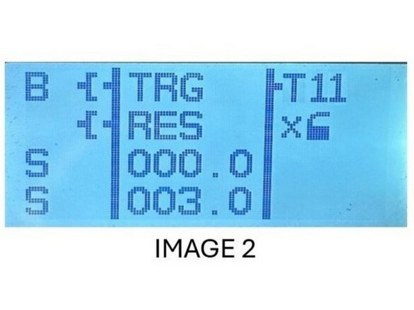
3) Now press the “Z3” button once, so the numerical value of “1” is highlighted with the cursor then press “ALT” to change the number to “11” using the “Z4” button. Once finished press the “ALT” button again.
-
4) With this screen present and verified with a “T11” in the upper right corner, press the “Z1” button 3 times until the cursor is on the bottom numerical value (represented by 003.0 in the image above), the open/close stroke duration setpoint.
-
5) To change this number press the “ALT” button once to edit the number, and once finished press the “ALT” button again to the save the number. To exit this menu press the “ESC” button twice.
-
At no point can the screen read 000.0 so adjust numbers accordingly when changing values.
-
-
-
T1: Close to Open Dwell - The T1 timer controls the amount of time the door takes to change directions from close to open.
-
For example, if the dwell timer is set to 3 seconds for T1, when the door is closing and the operator presses the open button, it will take 3 seconds for the open-door output to turn on. The dwell timer ensures that there is a sufficient pause, which helps in the smooth operation and prolongs the life of the motor.
-
T2: Open to Close Dwell - The T2 timer, also known as the dwell timer, controls the amount of time the door takes when changing directions from open to close. Typically, this should be the same value as T1.
-
T5: Auto Close Timer - The T5 timer is the auto close timer. The smart relay will initiate the countdown for this timer only when the door is in the open position. This timer can be customized to set the duration for which the door remains open before automatically closing.
-
T11: Time to Hit Open/Close Limit - This setting tells the controller how long (in seconds) it takes for the door to reach the open or close limit. You will need to record the time in which your door takes to make a full open stroke (from the fully closed position), and then set T11 to this value.
-
For example, if you measure that your door takes 10 seconds to go from the close limit to the open limit, set T11 to be 10.0.
-
Note: To change a setpoint of a respective timer, please follow the procedure documents in the “To Adjust the Auto Close Timer Setpoint “section, and change the numerical value of “T” to the particular timer.
-
-
-
To configure the Normally Closed (N/C) and Normally Open (N/O) limit outputs, follow these steps:
-
1. Press the "Alt" button, so the screen changes to keypad.
-
2. Press the Z3 button 5 times within a 5-second window to enable N/O Limit Outputs.
-
3. Repeat the same process to disable N/O Limit Outputs and enable N/C Limit Outputs.
-
4. A message will appear on-screen indicating the current status of the outputs.
-
Additionally, you can check the current state of outputs 3 and 4 by navigating to the system settings menu and selecting "Output Status." This will display whether each output is in an N/C or N/O configuration.
-
-
-
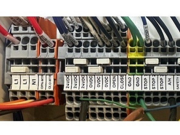
Hot Wire - Either L1 Terminal
-
Neutral Wire - N1
-
Ground - GND
-
-
-
Black Wire - OPN-MTR
-
Red Wire - CLO-MTR
-
White Wire - N1
-
Green Wire - GND
-
If motor runs in wrong direction, reverse black and red wires.
-
-
-
White Wire - 24VDC
-
Blue Wire - 0VDC
-
Brown Wire - 24VDC
-
Black Wire - Safety 1
-
Dark/Light Mode selection dial must be rotated fully counterclockwise
-
Gray Wire - NOT USED
-
You will need to remove the Factory jumper between 24VDC and SAFETY 1
-
-
-
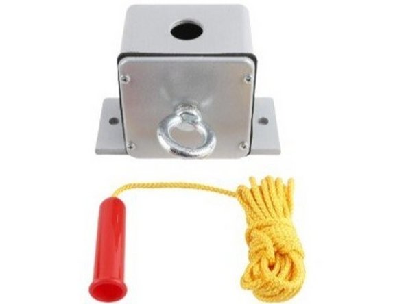
Receiver will be prewired from the factory, you will just need to terminate the wires in the Control Panel.
-
Red Wire - 24VDC
-
Blue Wire - 0VDC
-
White Wire - 24VDC
-
Green Wire - SEQ-OPN
-
-
-
Red Wire - 24VDC
-
White Wire - SEQ-OPN
-
-
-
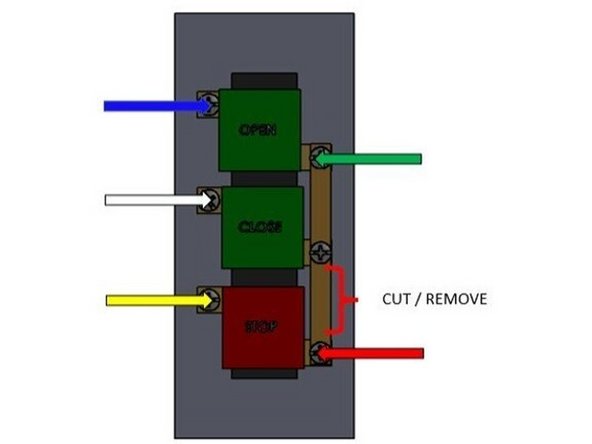
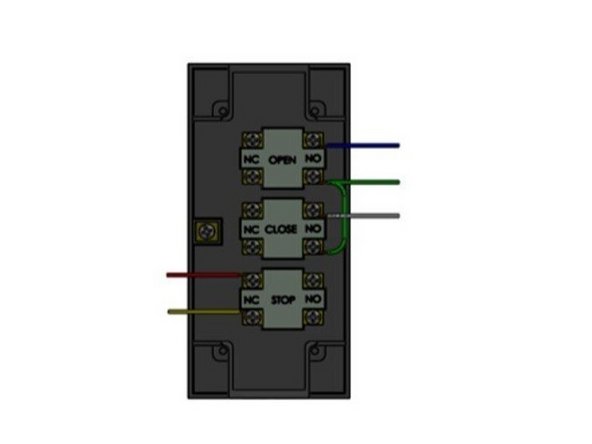
Cut the bonding strip between the close and stop button terminals as shown.
-
Green Wire - 24VDC
-
White Wire - CLOSE
-
Blue Wire - OPEN
-
Red Wire - STOP 1
-
Yellow Wire - 24VDC
-
This will be wired as a secondary button station, and you will need to remove the factory jumper between 24VDC and STOP 1.
-
-
-
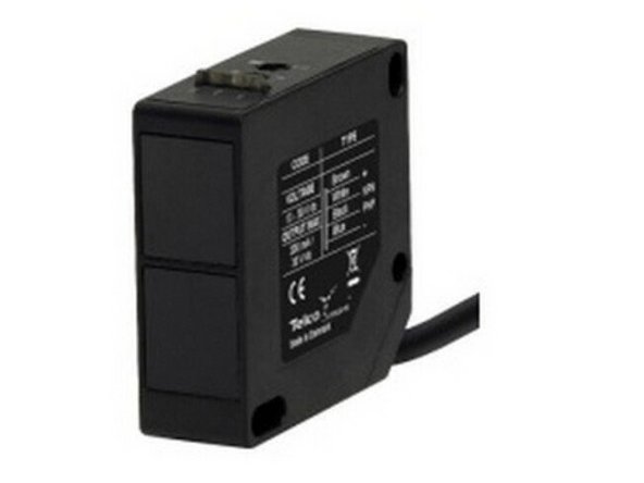
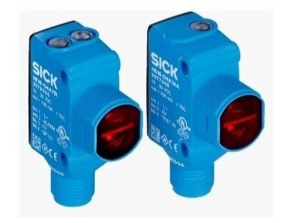
Transmitter: Can be identified by its single LED on top of the Unit
-
Receiver: Can be identified by its 2 LEDs on the top of the unit
-
Transmitter + Receiver: Brown Wires - 24VDC
-
Transmitter + Receiver: Blue Wires - 0VDC
-
Receiver: Black Wire - SAFETY 1
-
Receiver: White Wire - NOT USED
-
You will need to remove the factory jumper between 24VDC and SAFETY 1
-
-
-
This will be wired as a secondary or tertiary button station
-
Green Wire - 24VDC
-
White Wire - CLOSE
-
Blue Wire - OPEN
-
Red Wire - STOP 1
-
Yellow Wire - STOP 2
-
You will need to remove the jumper bar between STOP 1 and STOP 2
-


Team
