
Tools
Parts
- M8 x 1.25mm x 12mm Long Hex Bolts × 4
- M8 Split-Lock Washers × 4
- Machine Key
- Motor Mount Anti-Torque Bracket × 2
- M6 x 10mm Socket Cap Screw × 8
- M6 Split-Lock Washers × 8
- 5/16-18 x 1/2in Hex Bolt × 2
- 5/16 Flat Washer × 8
- 5/16 Split Lock Washer × 6
- 5/16-18 Hex Nut × 6
- 10-32 x 1/2in Machine Screw × 8
- Side-Mount Bracket × 2
- Control Panel Feet × 8
-
-
Technical Support Contacts:
-
Phone: 262-746-3374
-
Email: techsupport@goffscw.com
-
Website: http://www.goffsenterprises.com
-
-
-
Measure the Opening Width near the top of the Opening.
-
Divide that overall width measurement in half to find the Centerline location.
-
Clearly Mark the Centerline location.
-
-
-
The Header Measuring Process is identical for all Door Models. The Door Model you are installing may be different from the Model shown.
-
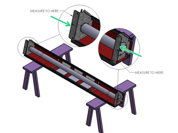
Place the Door roll Header Assembly across a safe and level work surface, and rotate the roll assembly frame so that the Header Bracket Mounting flanges are facing upward.
-
Measure the total width of the whole roll assembly from outermost edge of one Header Bracket’s Mounting flange to the outermost edge of the opposite side.
-
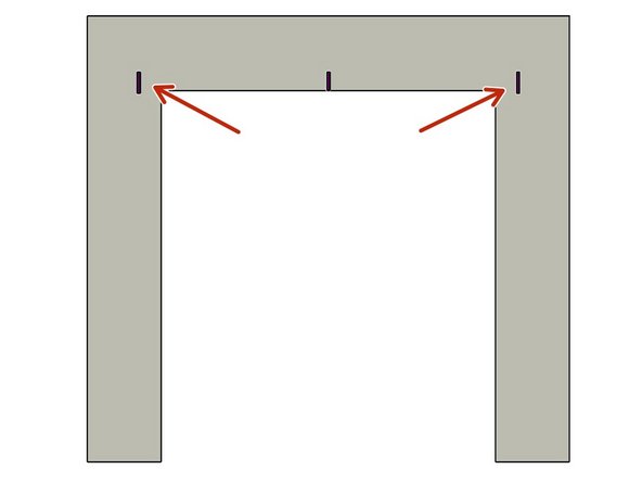
Divide that number by 2. This number is 1/2 of the Header Width, and is used to determine the Header location on the Left and Right Sides of the opening.
-
-
-
Mark this dimension on each side of the Opening Center mark.
-
-
-
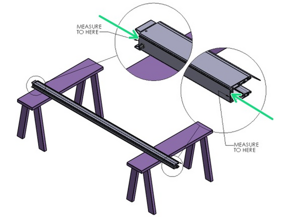
Lay one of the Vertical Track Assemblies on your work surface.
-
Measure the Length of the Aluminum Track only.
-
Add 1/4" to the Track dimension.
-
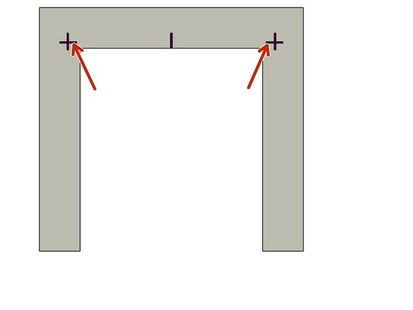
This is the Height dimension needed to mark the location of the Bottom edge of the Header Mounting Brackets.
-
-
-
Add a Horizontal line on each side of the Opening that intersects the previously drawn Vertical line.
-
-
-
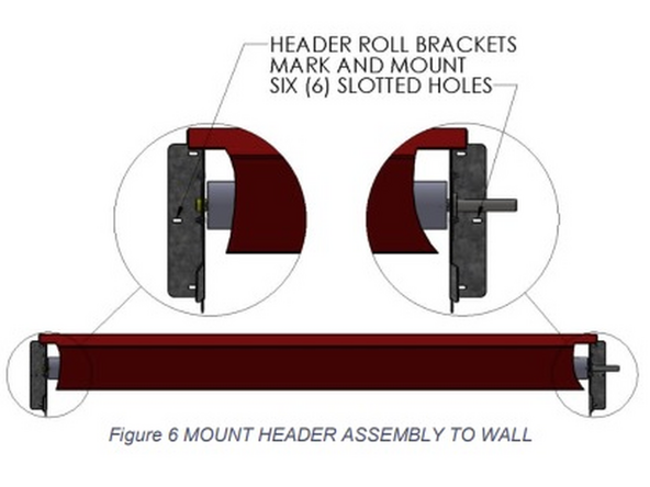
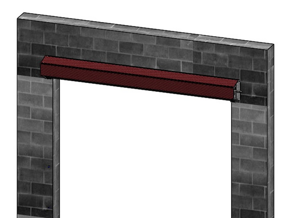
Using two (2) people, and two ladders at minimum, raise the Roll Header Assembly to fit between, and above, your markings on the wall.
-
Trace the insides of the Header Bracket’s three (3) mounting slots onto the wall surface.
-
Be sure that the Mounting Bracket’s bottom edge is on the height line, and that the outer edge is on your vertical/width line.
-
Predrill pilot holes for the mounting hardware at the centers of the traced locations. Using adequate mounting screws or bolts (depending on your building/surface material) to attach the Roll Header Bracket to each side of the opening.
-
Raise the Roll Header Assembly into place on the wall, and loosely secure with three (3) sets of mounting hardware per side using screws or bolts that are adequate to your building/surface material.
-
Check the Header Assembly for level, and fully tighten all six sets of hardware.
-
At this point leave the Roll Assembly tied off and held in place as it comes.
-
-
-
If you would like to mount the optional Track Extensions, please refer to the supplemental Track Extension installation instruction before proceeding. If not, proceed to the next step.
-
-
-
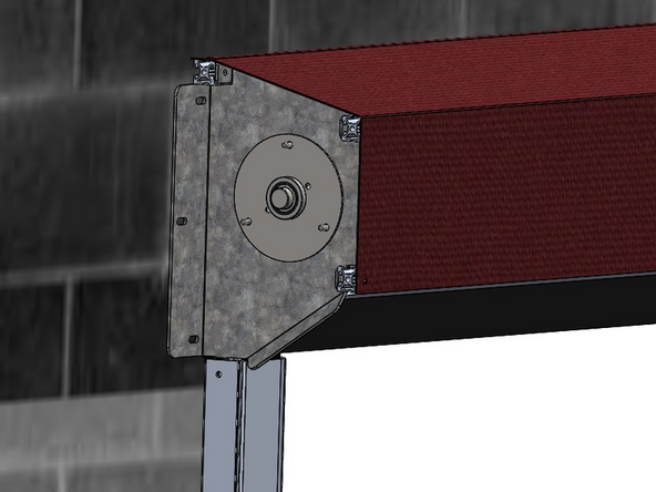
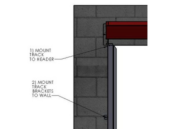
The Track mounts to the Outside of the Tab of the Header Mounting Bracket.
-
It is important to insert the Carriage Bolt from the Inside of the Header Bracket, and to install the Washer and Hex Nut on the Outside of the Track.
-
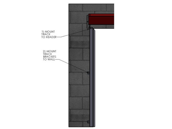
The Track must be plumb before securing it to the Mounting Surface.
-
-
-
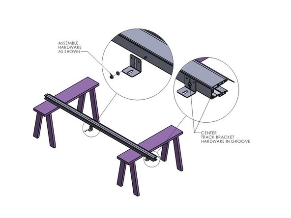
Attach a Track Mounting Bracket to the Track in the hole located at the bottom.
-
NOTE: For extreme cases, such as “High Wind Loads”, an additional Track Mounting Bracket (supplied) will be necessary.
-
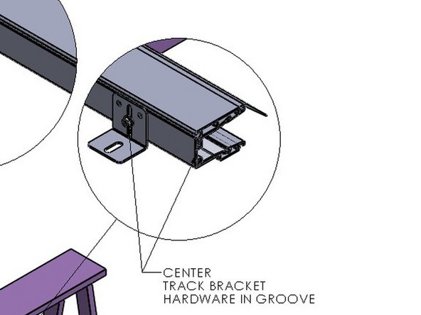
Mark and Drill the Track (.28-.31 dia) at 1.44” in from the front edge (i.e. centered in the groove), at about mid-height of the Track.
-
-
-
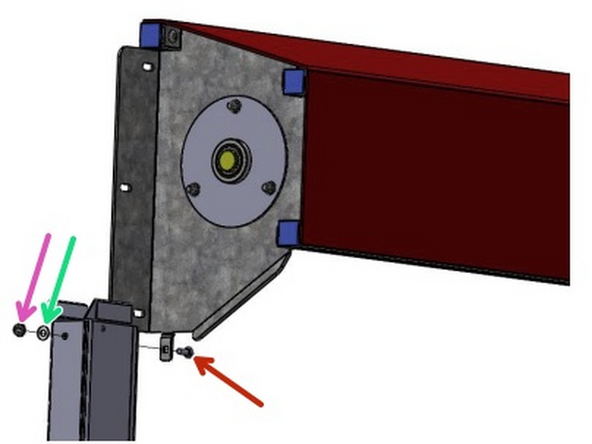
The Track assembly mounts to the outside of the tab of the Header Assembly Mounting Bracket.
-
Insert the Carriage Bolt through the Header Bracket Tab from the inside.
-
Move the Track to the Outside of the Header Bracket, then push the Bolt fully through the Square hole in the Tab and the Track.
-
Slide the Washer onto the Bolt from the outside of the Track.
-
Then snug the Hex Nut on the Bolt.
-
-
-
Plumb each Track.
-
Fasten the Tracks to the Mounting Surface through the Mounting Brackets.
-
Keep the Material and Roll-Tube tie wrapped until the Motor is Powered and ready to have the Limits Set.
-
-
-
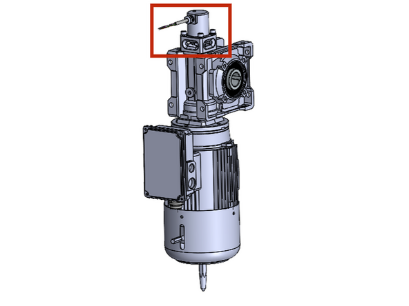
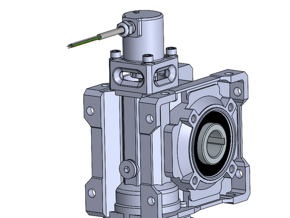
New Door Orders will come with the Encoder Mounted on the Motor from the Factory.
-
If you are replacing an encoder:
-
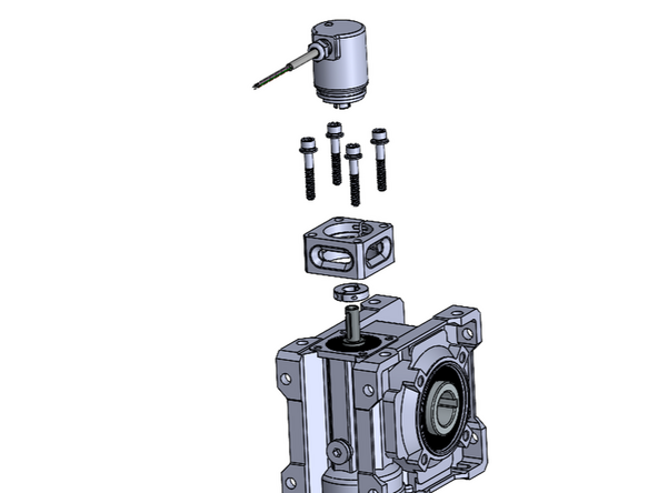
Install the Encoder Unit (with the clamp collar) into the Mount until it Falls/Locks into place and cannot Rotate within the Mount.
-
Install the Encoder and Mount Assembly onto the Motor Housing using the Provided Socket Cap Bolts and Lock Washers.
-
Make sure the Coupler on the Bottom of the Encoder, Fits over the Shaft on the Top of the Motor.
-
Tighten The set Screw on the Clamp Collar/Coupler to Positively Secure the Encoder to the Shaft so that they rotate together.
-
-
-
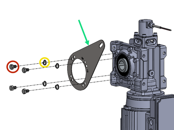
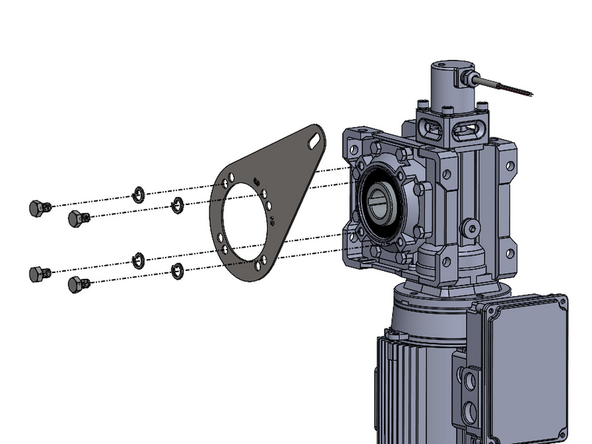
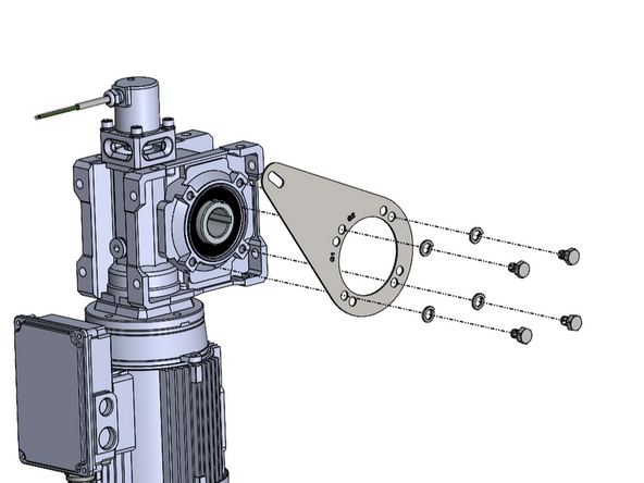
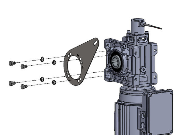
(4) M8 x 1.25mm x 12mm Long Socket Cap Screws
-
Requires 1/2in Socket or Wrench
-
(4) M8 Split-Lock Washers
-
(1) Motor Mount Anti-Torque Bracket
-
-
-
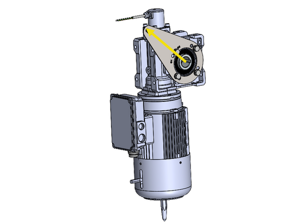
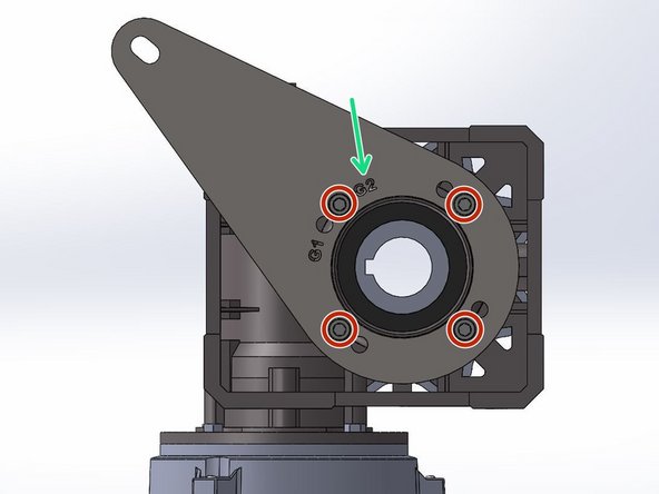
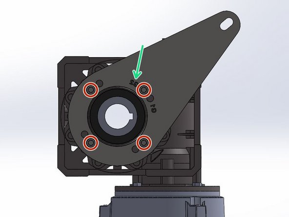
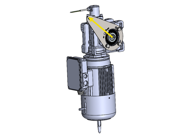
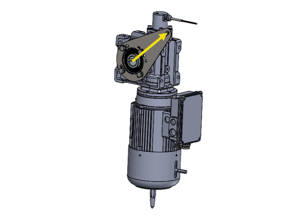
Note the Orientation of the Bracket in Relation to the Motor.
-
The Bracket has 2 Hole-Patterns Corresponding to G1 and G2 Doors. This ensures the proper Alignment when Installing the Motor Assembly onto a G1 or G2 Door.
-
For a G2 Door, Use the G2 Hole Pattern, and Vice Versa.
-
G1 Doors include Model 2000 and Clean Guard.
-
G2 Doors include Wash Guard, Harsh Guard and Machine Guard.
-
On a LH Drive, G2 Door, the Letters will Read Normally/Forward when the Bracket is Mounted onto the Motor.
-
Place the Bracket up on the Motor with the proper Hole Alignment.
-
Place the Lock Washer onto the Screw and Fasten the Bracket onto the Motor.
-
-
-
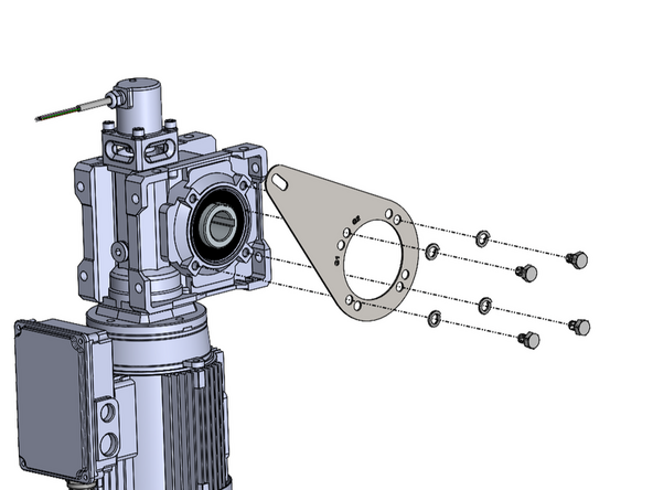
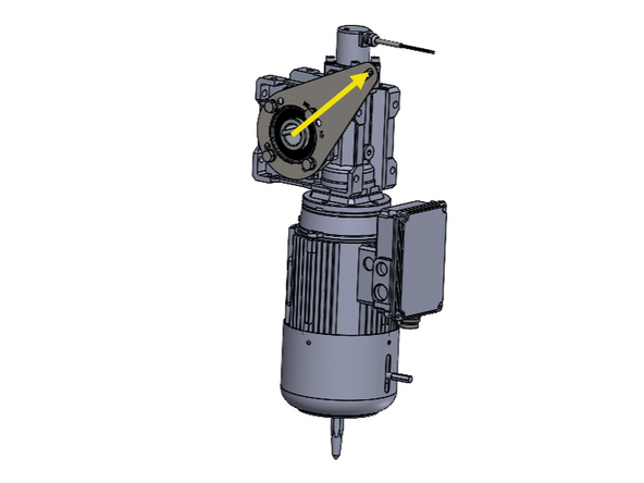
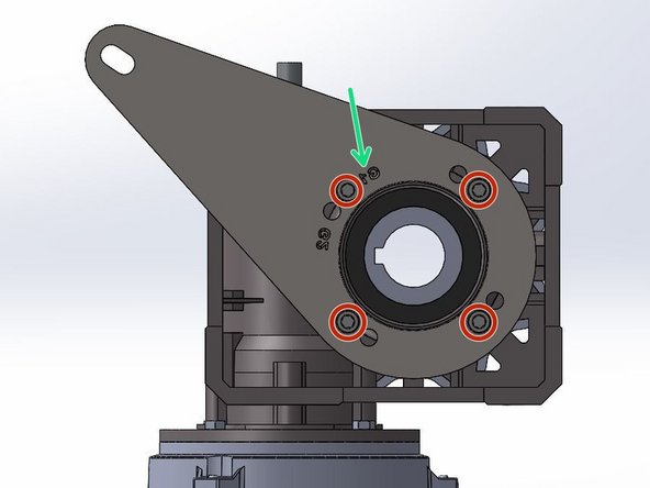
Note the Orientation of the Bracket in Relation to the Motor.
-
The Bracket has 2 Hole-Patterns Corresponding to G1 and G2 Doors. This ensures the proper Alignment when Installing the Motor Assembly onto a G1 or G2 Door.
-
For a G2 Door, Use the G2 Hole Pattern, and Vice Versa.
-
G1 Doors include Model 2000 and Clean Guard.
-
G2 Doors include Wash Guard, Harsh Guard and Machine Guard.
-
On a RH Drive, G2 Door, the Letters will Read Backwards when the Bracket is Mounted onto the Motor.
-
Place the Bracket up on the Motor with the proper Hole Alignment.
-
Place the Lock Washer onto the Screw and Fasten the Bracket onto the Motor.
-
-
-
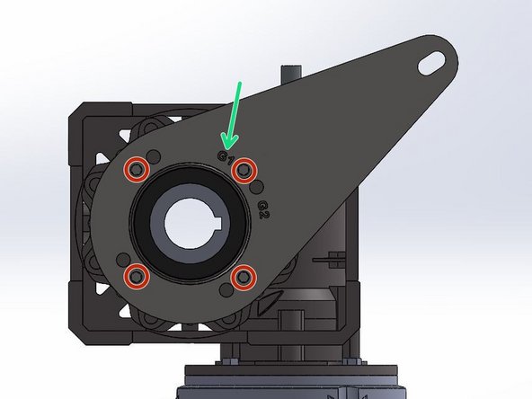
Note the Orientation of the Bracket in Relation to the Motor.
-
The Bracket has 2 Hole-Patterns Corresponding the G1 and G2 Doors. This ensures the proper Alignment when Installing the Motor Assembly onto a G1 or G2 Door.
-
For a G1 Door, Use the G1 Hole Pattern, and Vice Versa.
-
G1 Doors include Model 2000 and Clean Guard.
-
G2 Doors include Wash Guard, Harsh Guard and Machine Guard.
-
On a LH Drive G1 Door, the Letters will Read Backwards when the Bracket is Mounted onto the Motor.
-
Place the Bracket up on the Motor with the proper Hole Alignment.
-
Place the Lock Washer onto the Screw and Fasten the Bracket onto the Motor.
-
-
-
Note the Orientation of the Bracket in Relation to the Motor.
-
The Bracket has 2 Hole-Patterns Corresponding the G1 and G2 Doors. This ensures the proper Alignment when Installing the Motor Assembly onto a G1 or G2 Door.
-
For a G1 Door, Use the G1 Hole Pattern, and Vice Versa.
-
G1 Doors include Model 2000 and Clean Guard.
-
G2 Doors include Wash Guard, Harsh Guard and Machine Guard.
-
On a RH Drive G1 Door, the Letters will Read Normally/Forward when the Bracket is Mounted onto the Motor.
-
Place the Bracket up on the Motor with the proper Hole Alignment.
-
Place the Lock Washer onto the Screw and Fasten the Bracket onto the Motor.
-
-
-
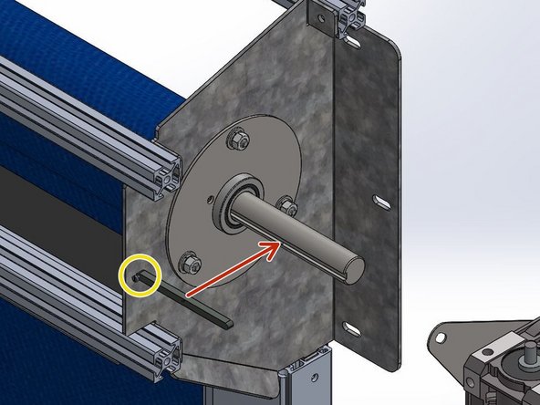
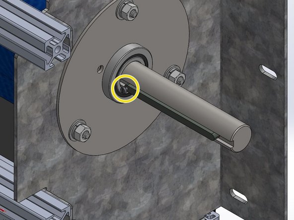
Install the Machine Key onto the Drive Shaft with the Set Screw Oriented Towards the Header (Between Motor and Door).
-
-
-
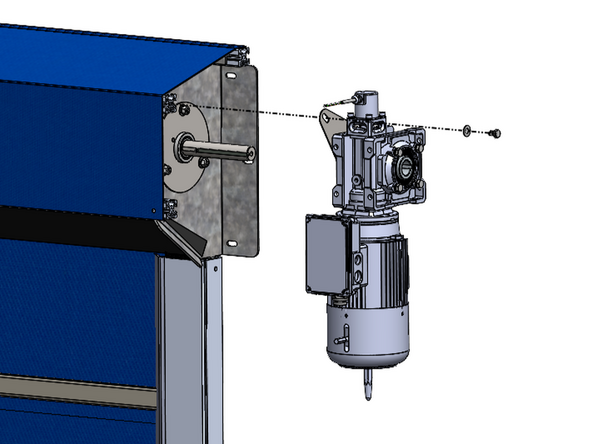
Slide the Motor onto the Shaft and Key.
-
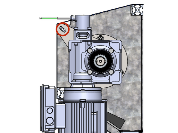
Tilt the Motor to Align the Hole in the Motor Mount Bracket with the Hole on the end of the Upper, Front Rail.
-
This should result in the Motor being oriented Vertically and Plumb (See Image 2).
-
Place the 5/16 Flat Washer onto the 5/16-18 x 1/2in Hex Bolt and Fasten the Motor to the Door with a Ratchet or Impact Driver.
-
-
-
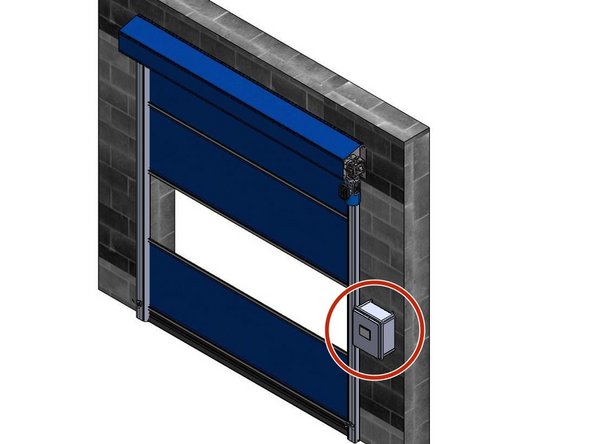
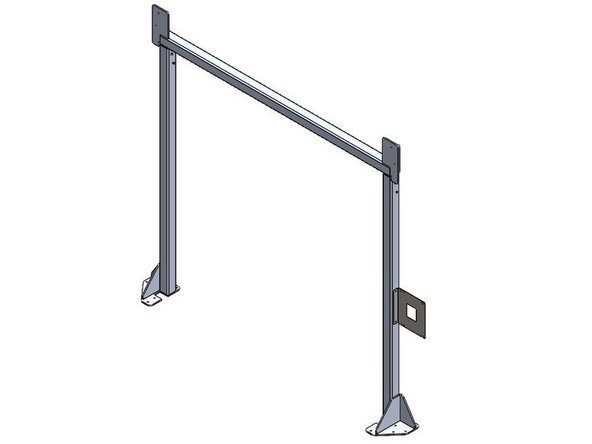
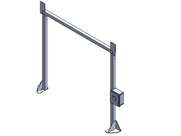
The Goff's ICS3 Control Panel can be Mounted in two different ways:
-
Flush Mounted on a Wall/Surface with the provided Feet.
-
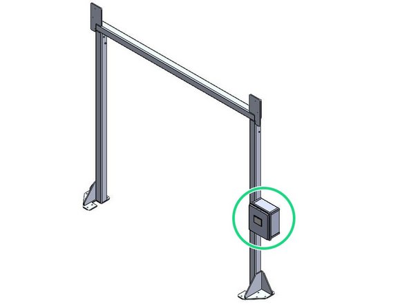
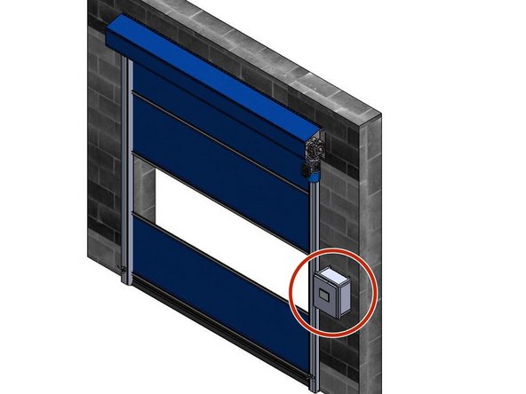
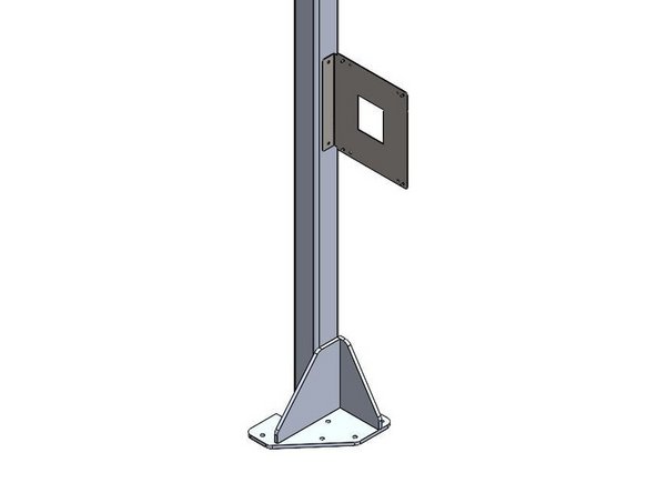
Mounted on a Door Frame with the provided Side-Mount Bracket.
-
Side-Mount Bracket only included when your door is ordered with a Door Frame.
-
-
-
Inside of the Goff's provided Control Panel, there will be a bag containing (4) Feet and (4) 10-32 x 1/2in Screws
-
There are (4) threaded inserts in the back of the Control Panel that will receive the 10-32 x 1/2in Screws.
-
Use these threaded inserts, to Fasten the provided Feet onto the Control Panel.
-
-
-
Goff's does not provide Fasteners for your Mounting Surface. It is up to you to determine the appropriate fasteners for the material you are mounting to.
-
With the appropriate Fasteners, Secure the Control Panel to the wall through the Feet.
-
The Control Panel can be Mounted at any Height or Location within 16ft of the Motor as the provided quick-connect motor cable is 16ft long.
-
If you need a longer cable for any reason, Goff's can provide it, but you will lose the quick-connect capability between the motor and panel. This means the panel will need to be wired into the motor in the field.
-
-
-
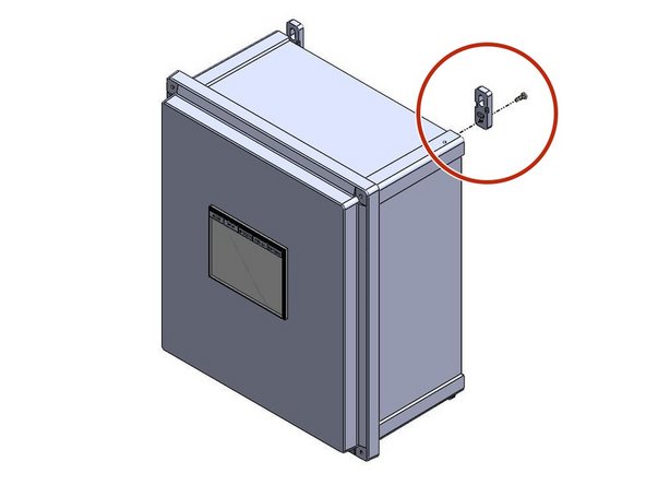
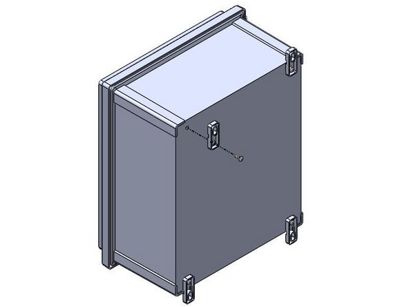
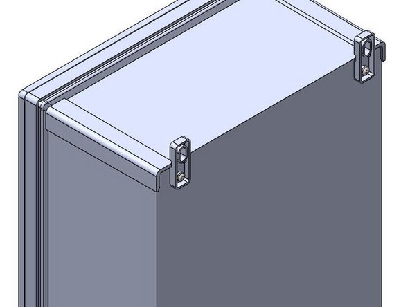
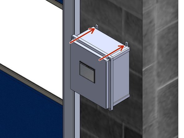
When Side-Mounting a Control Panel onto a Door Frame, the Bracket must be Mounted to the Door Frame Before the Control Panel can be Mounted to the Bracket.
-
Goff's will provide (2) Self-Drilling Fasteners to use for Mounting the Bracket to the Door Frame.
-
The Bracket/Control Panel can be Mounted at any Location on the Door Frame as long as the 16ft quick-connect Cable from the Control Panel can reach the Motor.
-
If you need a longer cable for any reason, Goff's can provide it, but you will lose the quick-connect capability between the motor and panel. This means the panel will need to be wired into the motor in the field.
-
The Bracket can be Flipped to allow Left- or Right-Hand Mounting.
-
-
-
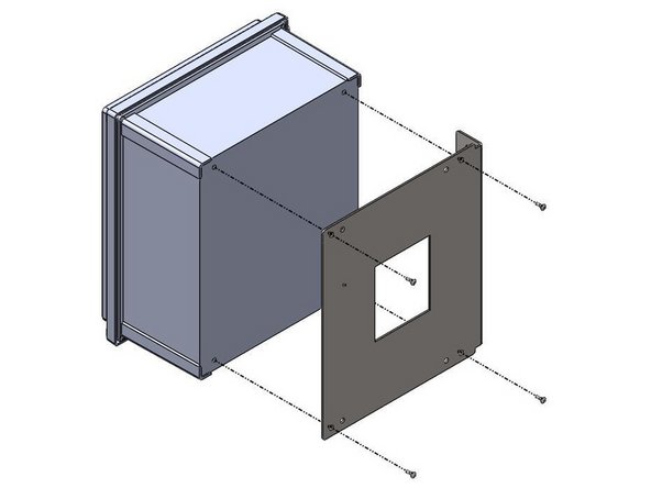
Inside of the Control Panel, there will be a bag containing (4) 10-32 x 1/2in Screws
-
These Screws will be needed to Install Control Panel onto the Side-Mount Bracket.
-
There are (4) threaded inserts in the back of the Control Panel that will receive the 10-32 x 1/2in Screws.
-
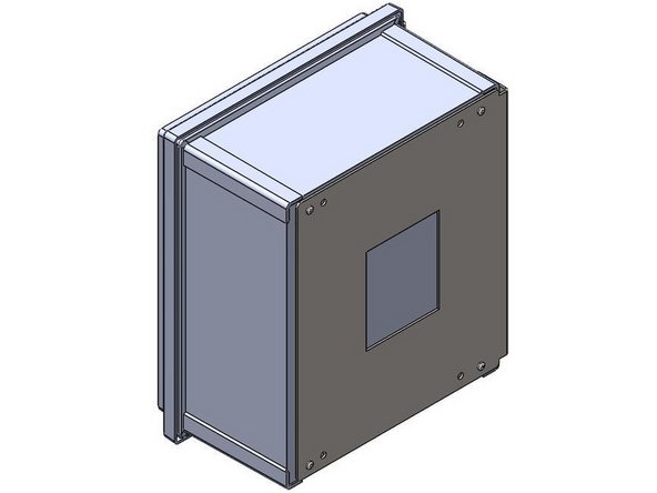
Use the Outer-Most Hole Pattern on the Side-Mount Bracket to ensure proper hole alignment with the Control Panel. Use these threaded inserts, to Fasten the Control Panel onto the Side-Mount Bracket.
-
-
-
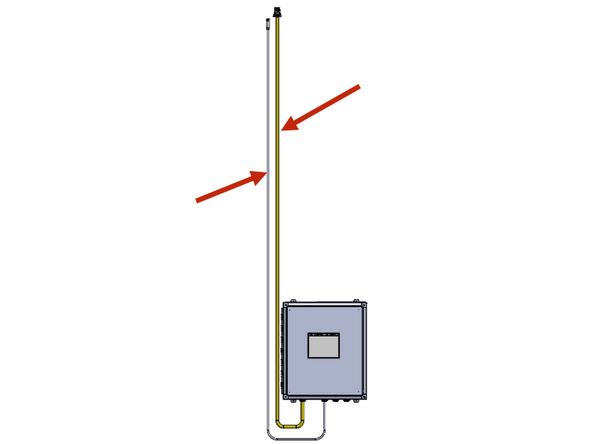
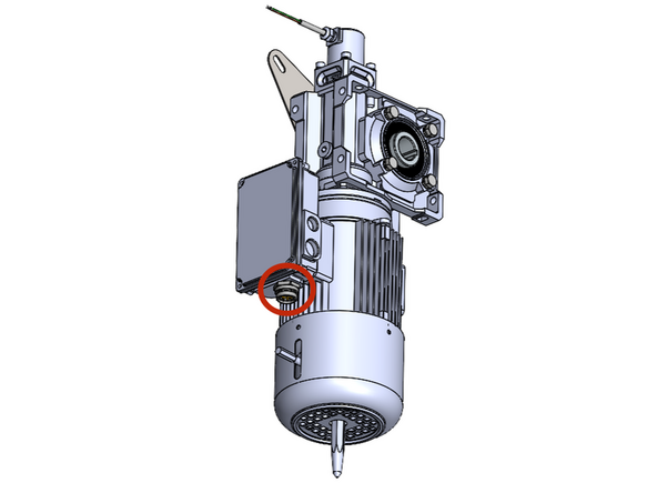
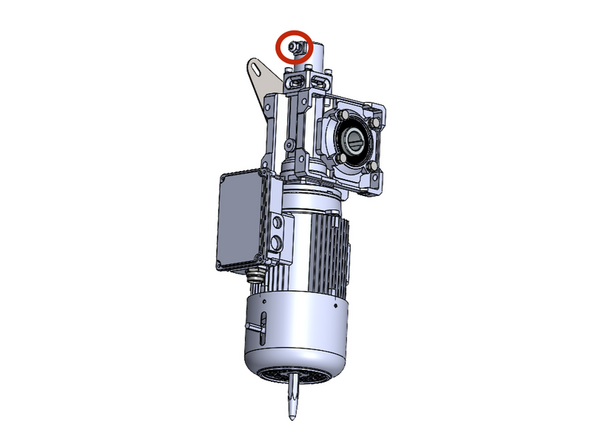
From the Factory, your Goff's Supplied Control Panel will have (2) Cables coming out of it. The yellow cable is for the motor, and the other smaller cable is for the encoder. These cables are equipped with quick-connect threaded plugs that will thread into a receptacle on the motor and encoder.
-
This motor cable is 16ft long. Make sure to mount the panel in a location where the cable can reach the motor.
-
If you need to shorten this cable, do it from the end terminated inside the control panel.
-
If you need a longer cable for any reason, Goff's can provide it, but you will lose the quick-connect capability between the motor and panel. This means the panel will need to be hard-wired into the motor in the field.
-
Make the connections at the motor and encoder.
-
It is critical to keep the high voltage motor cable, and the low voltage encoder cable separated and not tied together.
-
-
-
IF THIS IS A NEW DOOR AND THE ENCODER IS ALREADY MOUNTED ON THE MOTOR, SKIP THIS STEP. If you are replacing an encoder, tap the following series of Buttons to get from the Home Screen to the Limit-Setting Screen:
-
Setup And Diagnostics
-
Setup > Settings > Next Screen
-
Encoder Calibration
-
First we need to scale the encoder. We do this by running the door
-
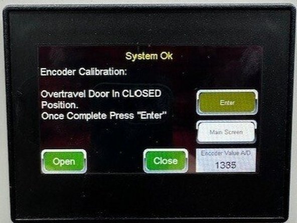
(Image 1) First, run the door down slightly past the desired close limit position (a few inches is enough). Hit Enter and wait for the screen to switch.
-
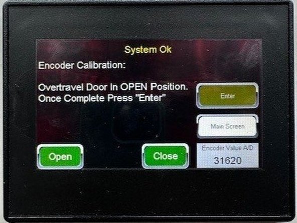
(Image 2) When the screen changes, run the door open slightly past the desired open limit position (a few inches is enough). Hit Enter and wait for the screen to switch.
-
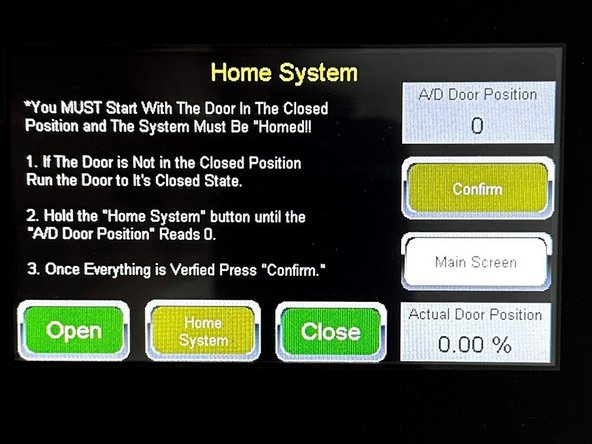
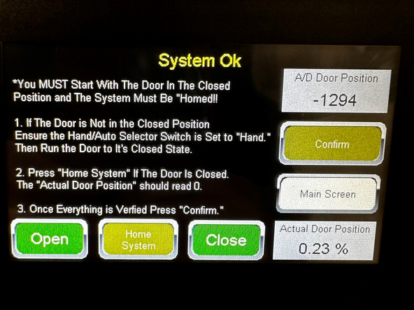
Once the screen changes again, proceed to the next step of this guide.
-
-
-
For new doors that already have the encoder mounted on the motor, press the following series of buttons to get to the limit setting screen(s):
-
Setup & Diagnostics
-
Setup
-
Quick Setup
-
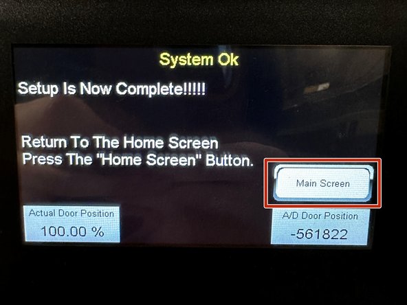
Now, simply Follow the On-Screen Prompts to Teach the Open- and Closed-Limits positioned exactly as you want them.
-
Once Complete. Press the "Main Screen" Button.
-
You are now ready to Operate your Goff's Door.
-



Team
