-
-
Technical Support Contacts:
-
Phone: 262-746-3374
-
Email: techsupport@goffscw.com
-
Website: http://www.goffsenterprises.com
-
-
-
Measure the Opening Width near the top of the Opening.
-
Divide that overall width measurement in half to find the Centerline location.
-
Clearly Mark the Centerline location.
-
-
-
The Header Measuring Process is identical for all Door Models. The Door Model you are installing may be different from the Model shown.
-
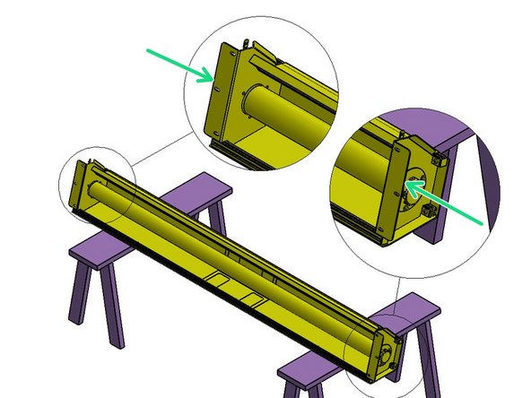
Place the Door roll Header Assembly across a safe and level work surface, and rotate the roll assembly frame so that the Header Bracket Mounting flanges are facing upward.
-
Measure the total width of the whole roll assembly from outermost edge of one Header Bracket’s Mounting flange to the outermost edge of the opposite side.
-
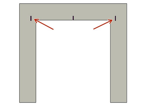
Divide that number by 2. This number is 1/2 of the Header Width, and is used to determine the Header location on the Left and Right Sides of the opening.
-
-
-
Mark this dimension on each side of the Opening Center mark.
-
-
-
The Track Measuring Process is identical for all G1 Door Models. The Door Model you are installing may be different from the Model shown.
-
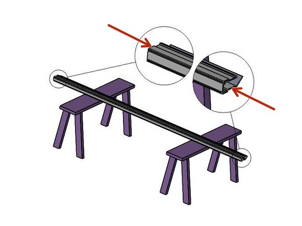
Set one of the Vertical Track Assemblies on your work surface.
-
Measure the Length of the Vinyl Track only.
-
ADD 3-1/4” to this number and take note.
-
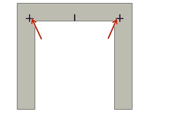
This is the Height dimension needed to mark the location of the Bottom edge of the Header Mounting Brackets.
-
-
-
With the Calculated number (Track length + 3-1/4"), add a Horizontal line on each side of the Opening that intersects the previously drawn Vertical line.
-
-
-
Use two (2) people, and two ladders (at minimum).
-
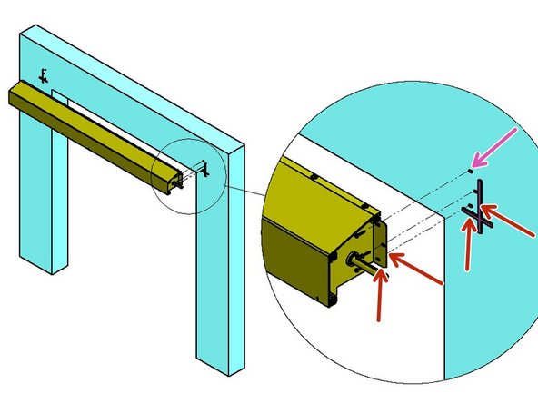
Raise the Roll Header Assembly into place on the wall.
-
The bottom and outside edges of the Header Mounting Brackets should fit inside of Marks on the Mounting Surface.
-
Transfer the (3) Slot locations, per side, onto the Mounting Surface.
-
Prepare the locations for Hardware appropriate to the building material.
-
Loosely secure with three (3) sets of mounting hardware per side.
-
Level the Header Assembly, and fully tighten all six sets of hardware.
-
At this point leave the Door/Web Roll tied off and held in place as it comes.
-
-
-
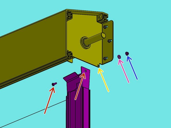
The Track Transition Bracket mounts to the Inside of the tab of the Header Assembly Mounting Bracket.
-
It is important to insert the Carriage Bolt from the inside of the Transition Bracket and the Washer and Hex Nut on the outside of the Header Bracket.
-
The Track must be plumb before securing it to the Mounting Surface.
-
-
-
The Track assembly mounts to the Inside of the Header Assembly Mounting Bracket.
-
From the inside of the Track, Insert the Carriage Bolt fully through the Square hole.
-
Move the Track to the Inside of the Header Bracket, then push the Bolt through the Square hole in the Tab.
-
Slide the Washer onto the Bolt from the outside of the Header Bracket.
-
Then snug the Hex Nut on the Bolt.
-
-
-
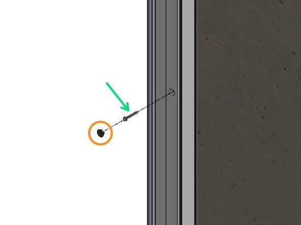
Remove the Black Plastic Plugs from the Track front. These are Mounting access Holes.
-
Use a Level to Plumb the Track and Transfer the Mounting Hole locations onto the Mounting Surface.
-
Remove the Track, and Prepare these locations for Hardware Appropriate to the Building Material.
-
Most Materials will Require Pre-Drilling Holes to Accept the Necessary Hardware.
-
With the Track Assembly Reinstalled and “Hanging” in this position, Plumb the Track to make sure it is Vertically Aligned.
-
Secure the Tracks to the Wall with Hardware Appropriate for your Mounting Surface Material.
-
Replace Plastic Caps.
-
-
-
Carefully remove the Operator from its Shipping Carton, and Remove the Fasteners that secure the Operator to the Backing Plate (plywood).
-
Open the Accessory Box and locate the 14 Tooth output Sprocket and ¼” Key (if not already installed).
-
Install the Sprocket on the Operator Output Shaft and tighten firmly.
-
It is important to install the Sprocket before the Operator is Mounted to your Mounting Surface/Wall.
-
-
-
The Operator (Motor and Reduction Assembly) will be secured to your Building Fascia using 5/16” Fasteners (bolts, lag screws, studs, etc..).
-
Select fasteners that are not only right for your specific Building Material, but also that can endure Repeated Loosening and Tightening.
-
It may be necessary to Loosen/Tighten these Fasteners a number of times in order to achieve proper initial Chain Tension and to later adjust for Chain Stretch and Wear.
-
The use of Washers between the Heads of the Fasteners and the Metal Brackets on the Operator is Strongly Recommended.
-
-
-
Tape the two pieces of the Operator Installation Template together making sure to properly align the Index Mark (bottom of page #1, top of page #2).
-
Cut along the indicated Dotted Lines and Remove the section of the Template that corresponds to the Right-Hand Mounting Bracket. of the upper box assembly
-
Align the Template with the Right Header Bracket on the Upper-Box Assembly and Transfer the four (4) Hole Locations for the 5/16” Fasteners to your Building Fascia.
-
Carefully lift the Operator in place and Secure it to your Building using four 5/16” Fasteners. Do not fully tighten the Fasteners at this Point.
-
Slide the Operator “up” until the Fasteners are at the Bottoms of the Mounting Slots, and Tighten the Fasteners Snugly enough to stop the Operator from Sliding back Down.
-
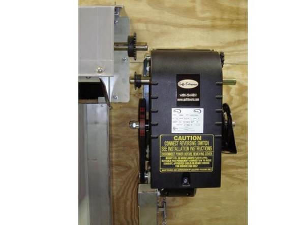
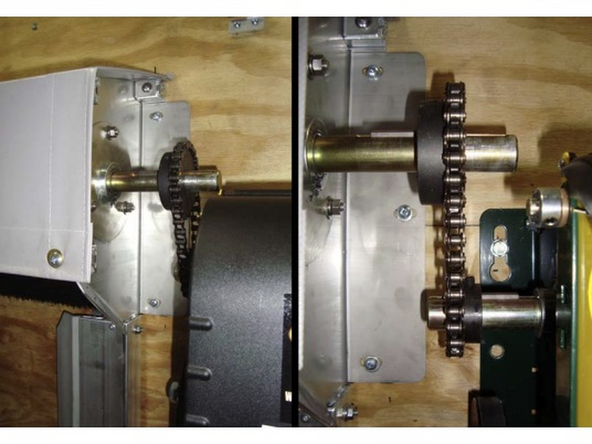
Your installation should resemble the following photo
-
-
-
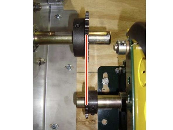
Check the Alignment of the two Sprockets.
-
They should be in direct Vertical Alignment. If not, Loosen the Set Screws on either of the Sprockets and Adjust its Position until it is in line with the other Unit.
-
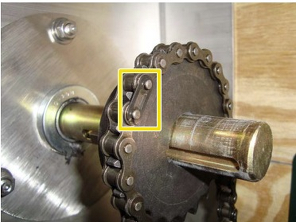
Locate the #41 Chain and Install it over the two Sprockets. Secure the ends with the included Master Link.
-
Loosen the four Fasteners that Secure the Operator to the building Fascia and allow the Weight of the Operator to establish the Tension in the Chain.
-
Make sure that the Front and Rear runs of the Chain are “Taught” (slightly rotate the roller tube by hand if necessary).
-
Make sure that the Sprockets are still in Alignment and Tighten the four Fasteners.
-
-
-
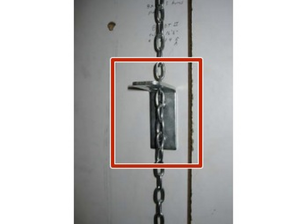
Mount the Chain Bracket to the building Wall directly below the Release-Chain at a convenient Elevation (usually about 4’ from the floor). Route the Release-Chain through the Keyhole Slot.
-
The Release-Chain can be Trimmed to-Length at any point below the Keeper. We have also included a “T-Handle” which can be optionally Installed below the Chain Bracket. Please see the Operator Instruction Manual for additional Details.
-
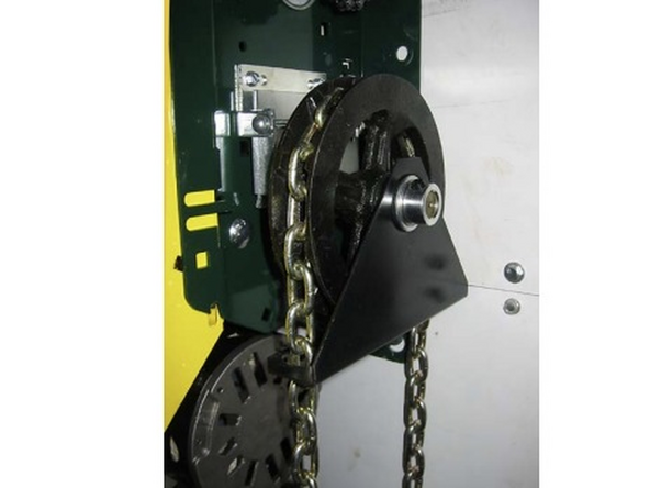
Route the Hoist Chain over the Hoist Chain Sprocket (Image 2).
-
Join the Free ends of the Chain by Opening one of the Links.
-
The Chain may be Shortened as required to avoid Dragging on the Ground.
-
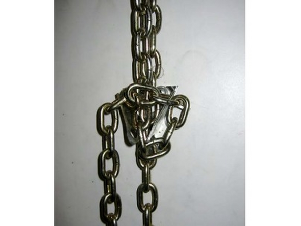
Secure both Runs of Chain to the Keeper by Routing it as shown in the Image 3.
-
The chain MUST be properly secured before going to the next assembly steps.
-
-
-
Open the Operator's Cover.
-
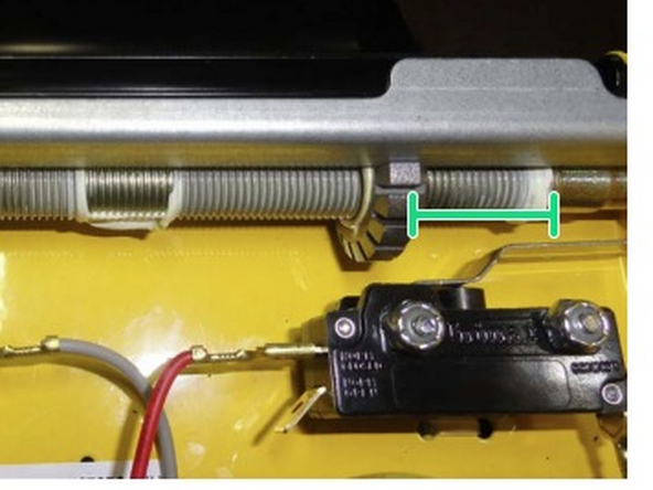
The next Steps will involve Pre-Setting the End Stop (limit) Nuts on the Operator.
-
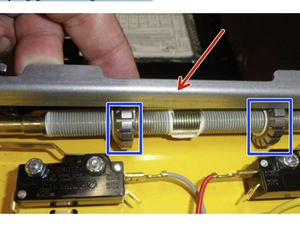
To do this, Lift the Locking Bar out of the way to allow the Notched Nuts to Spin.
-
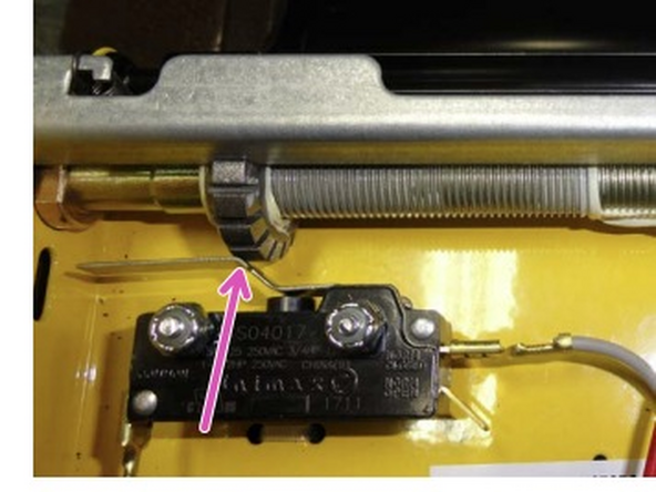
Then Rotate the Metal Notched Nuts until they hit their respective Limit Switch.
-
When adjusting an End-Stop, make sure that the other end stop does not accidentally Rotate.
-
Pre-set the “OPEN” (left) End-Stop so that the Nut is Flush with the Left End of the Threaded Rod.
-
Pre-set the “CLOSE” (right) End-Stop so that the Nut is approximately 1.5” (one and a half inches) from the Right End of the Threaded Rod.
-
When you are done, make sure that the Notches on both Nuts properly Engage the Locking Lever Bracket.
-
-
-
The next step involves releasing the operator brake and using the chain hoist.
-
Whenever the Operator's Brake is Released, it is important to have the Hand-Chain Secured to the Bracket or held Firmly.
-
The door is not Counter-Balanced, and Failing to Secure the Hand-Chain may allow the Door to Unroll Rapidly, causing Damage to the Assembly.
-
-
-
Remove the Safety/Shipping Vinyl strapping from the Door Roll.
-
Pull down on the Release-Chain until a firm Resistance is felt. This will release the Operator Brake and engage the Chain Hoist.
-
Use the Keyhole feature in the Chain Bracket to hold the Release-Chain in this position. Carefully unhook the Hand Chain from the Bracket and use the Hoist feature to Lower and Raise the Door.
-
As required, Guide the bottom of the Vinyl Door into the Vertical Track Extrusions. Observe the door action and look for any Binds or Interferences that Hinder the Operation of the Door.
-
Resolve any issues before proceeding on to the next steps. Run the Door Up and Down a number of times with the Chain Hoist. This will allow the Vinyl Door to “relax” and conform to the Roll-Tube. Position the door in the approximate Mid-Point (halfway open) Position, and Re-Secure the Hand Chain to the Bracket and Unlock the Release-Chain.
-
Almost done!
Finish Line


