
-
-
Technical Support Contacts:
-
Phone: 262-746-3374
-
Email: techsupport@goffscw.com
-
Website: http://www.goffsenterprises.com
-
-
-
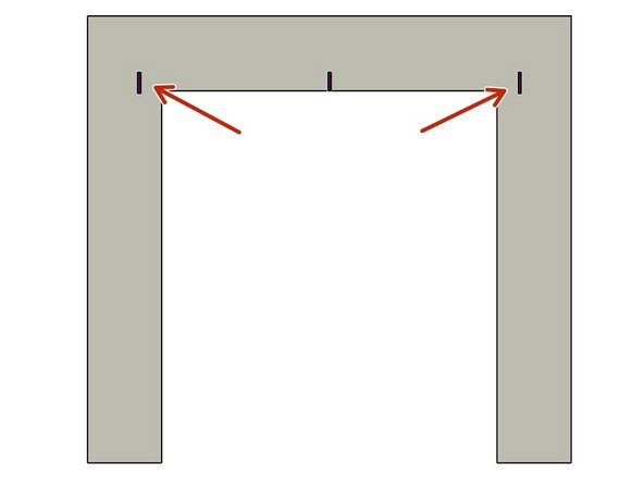
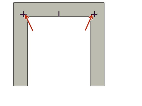
Measure the Opening Width near the top of the Opening.
-
Divide that overall width measurement in half to find the Centerline location.
-
Clearly Mark the Centerline location.
-
-
-
The Header Measuring Process is identical for all Door Models. The Door Model you are installing may be different from the Model shown.
-
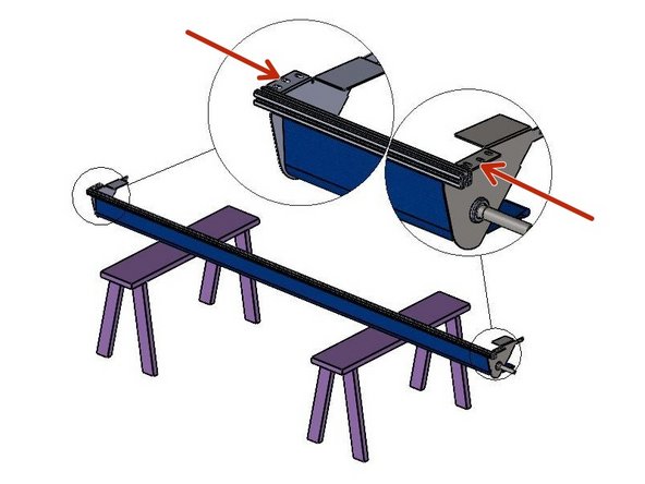
Place the Door roll Header Assembly across a safe and level work surface, and rotate the roll assembly frame so that the Header Bracket Mounting flanges are facing upward.
-
Measure the total width of the whole roll assembly from outermost edge of one Header Bracket’s Mounting flange to the outermost edge of the opposite side.
-
Divide that number by 2. This number is 1/2 of the Header Width, and is used to determine the Header location on the Left and Right Sides of the opening.
-
-
-
Mark this dimension on each side of the Opening Center mark.
-
-
-
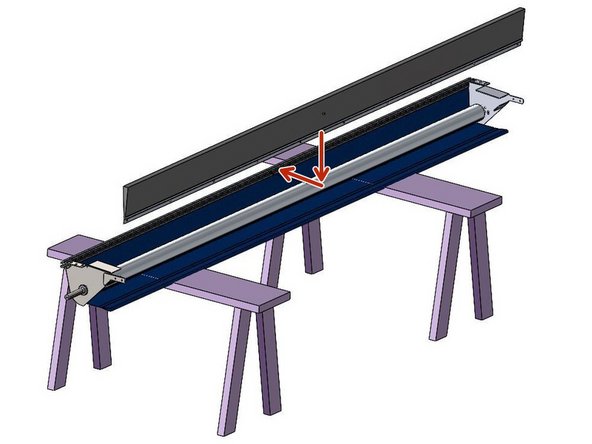
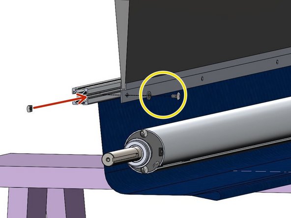
While your Door Header is still on the Saw-Horses, it is the best time to also Install the Projection-Mount Brush Assembly.
-
The Brush Assembly Installs on the Underside of the Back Piece of Header Rail, with the Brush facing the Opening.
-
-
-
Count the Number of Holes that are Pre-Drilled into the Brush Assembly's Retainer.
-
This is how many 1/4-20 Fasteners you will need to use to Install the Brush Assembly.
-
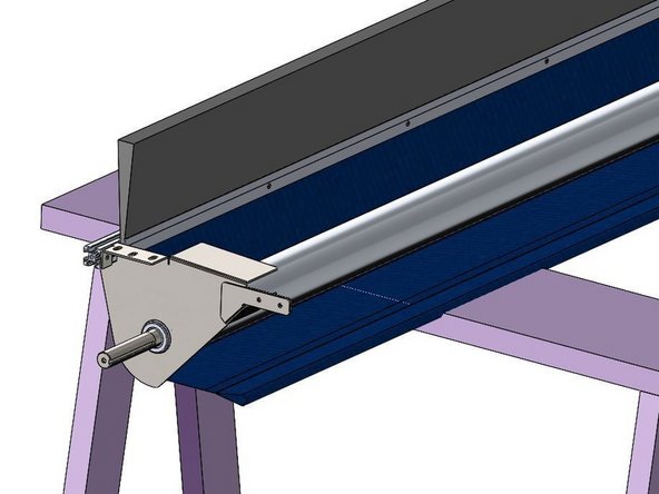
Slide the 1/4-20 Square Nuts into the Channel on the Underside of the Rear Header Rail.
-
Make sure each Square Nut lines up with a Pre-Drilled Hole in the Brush Retainer.
-
NOTE: Header Bracket Omitted for Clarity.
-
Place the 1/4" Flat Washers onto the 1/4-20 Screws, and Fasten them Through the Brush Retainer, into the Square Nuts.
-
-
-
The Track Measuring Process is identical for all G1 Door Models. The Door Model you are installing may be different from the Model shown.
-
Set one of the Vertical Track Assemblies on your work surface.
-
Measure the Length of the Vinyl Track only.
-
ADD 5-3/4” to this number and take note.
-
This is the Height dimension needed to mark the location of the Bottom edge of the Header Mounting Brackets.
-
-
-
With the Calculated number (Track length + 5-3/4"), add a Horizontal line on each side of the Opening that intersects the previously drawn Vertical line.
-
-
-
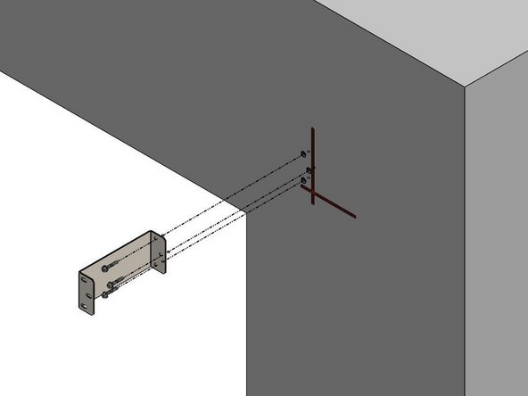
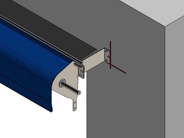
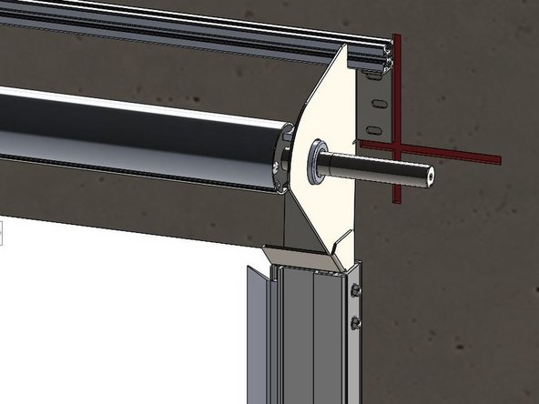
Orient the slotted end of the Header Mounting Projection Bracket against the Mounting Surface.
-
Orient the flange outward.
-
Align the Bottom surface of the Header Mounting Bracket with the Horizontal line on the Mounting Surface.
-
Align the Outer edge of the Header Mounting Bracket with the Vertical line on the Mounting Surface.
-
Trace the slotted mounting slots onto the Mounting Surface.
-
-
-
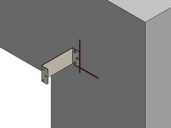
Loosely fasten Bracket to the Mounting Surface with appropriate hardware.
-
Plumb the Bracket.
-
Tighten Hardware securely.
-
Repeat for the other Header Mounting Bracket.
-
-
-
Use two (2) people, and two (2) Ladders at minimum to Install the Roll Header Assembly
-
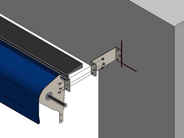
Raise the Roll Header Assembly into place on the Projection Brackets.
-
Loosely Tighten with three (3) sets of ¼-20 Screws, Flat Washers and Hex Nuts per side.
-
Do not fully tighten the Hardware until the Header Assembly Brackets are Aligned and Plumb with the Projection Brackets.
-
Check the Header Assembly for Level, and make any necessary final Adjustments.
-
Once aligned, fully Tighten all six sets of Hardware.
-
At this point leave the Roll/Web Assembly tied off and held in place as it comes.
-
-
-
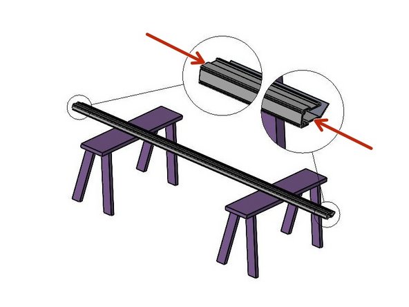
Tracks are marked for orientation as Left Side, and Right Side.
-
Lay the two Vertical Track Assemblies on your work surface.
-
Un-roll the Side Seal material.
-
Remove the Plugs from the front of the Track
-
Locate the Track Projection Mount Brackets, four (4) per Track.
-
Locate four the ¼-20 Screws and Flanged Nuts.
-
-
-
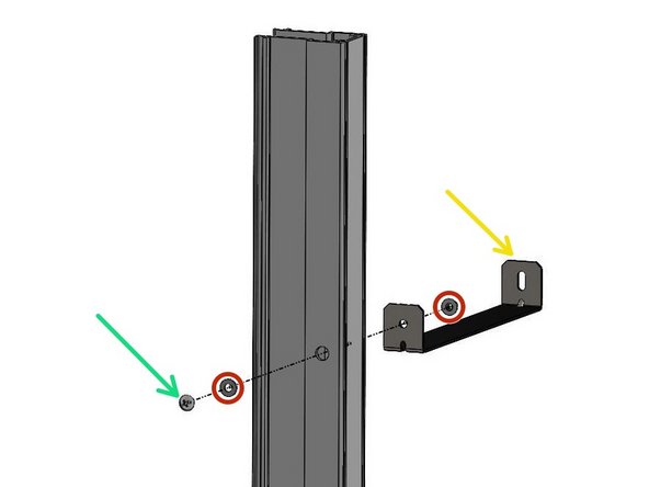
Push a screw through the hole in the back surface from the inside of the Track.
-
Slip the Projection Bracket onto the 1/4-20 Screw, with the hole facing the Track, and then thread the nut, onto the screw.
-
The slotted end of the Projection Bracket will fasten to the Mounting Surface in a later step.
-
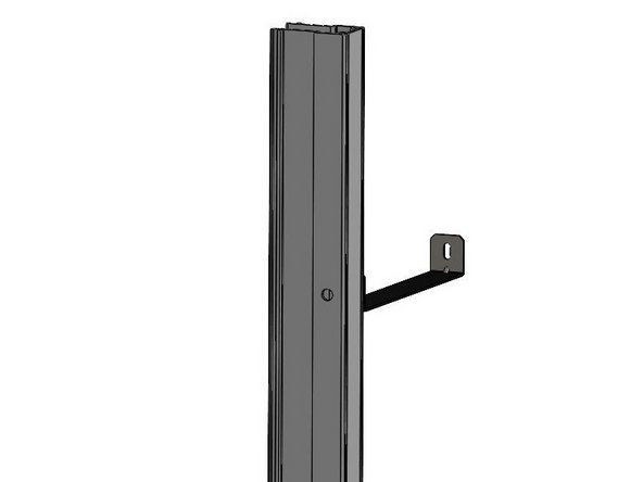
These Brackets should be Mounted so that their Flanges point Vertically (as shown).
-
Fully tighten the hardware for these brackets once they are aligned with the Track edges.
-
Re-install the Plug Caps into the hardware access holes on the front side of the Tracks.
-
-
-
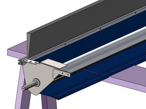
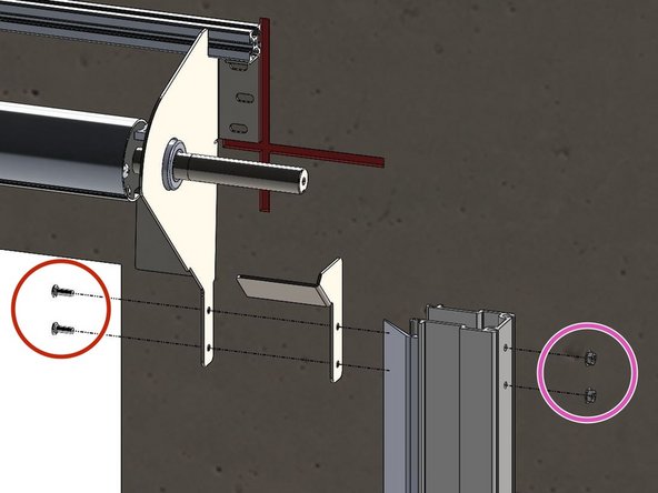
The Track Assembly Mounts to the Outside of the Header Mounting Bracket, with the Transition Bracket Sandwiched in the Middle.
-
Insert the (2) Carriage Bolts so that they pass through the Holes in the Header Mounting Bracket, Transition Bracket, and Vertical Track Assembly.
-
Then snug the Hex Nut on the Bolt from the Outside.
-
-
-
Vinyl Critter Catchers Omitted from this step for Clarity.
-
Plumb the Tracks and Transfer All Mounting Hole locations onto the Mounting Surface.
-
There are 8 Track Brackets (4 per Track).
-
Swing the Tracks out of the way, and Prep these locations for Hardware Appropriate for the Building Material.
-
Pre-Drilling Holes in the Mounting Surface is Recommended.
-
Swing the Tracks back into place, Plumbing them once again, before finally, Fastening the Track Brackets to the Mounting Surface.
-
-
-
The Vinyl Critter Catchers are installed in the Vertical Track prior to shipment. Once the Vertical Tracks are installed, it is time to seal up the sides of the Door, back to the Mounting Surface.
-
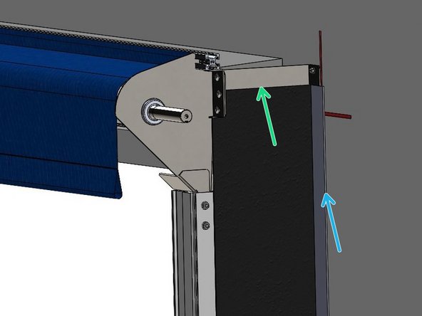
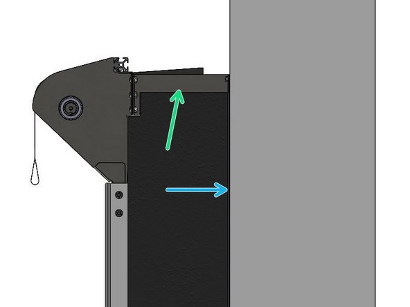
Secure the top edge of the Side Seal to the Header Projection Brackets via the hook-and-loop strips (provided).
-
Pull the Material up and back to ensure it is Taut in all directions to close any Air Gaps that remain.
-
Fold the Side Seal Material to flatten it against the wall. Secure it through the Material into the Mounting Surface with appropriate Hardware.
-
-
-
Vinyl Critter Catchers Omitted for Clarity.
-
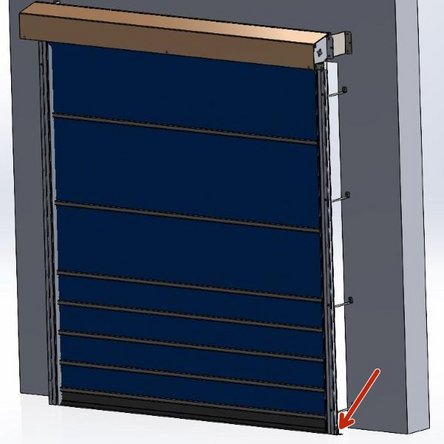
Installing this Provided Kit is Recommended by Goff's.
-
The purpose of this Kit is to Anchor the Vertical Tracks to the Floor to completely inhibit their ability to move left and right.
-
-
-
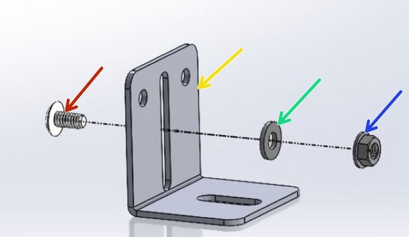
What you will Receive:
-
L-Bracket
-
1/4-20 Machine Screw
-
1/4in ID Flat Washer
-
1/4-20 Serrated Flange Nut
-
-
-
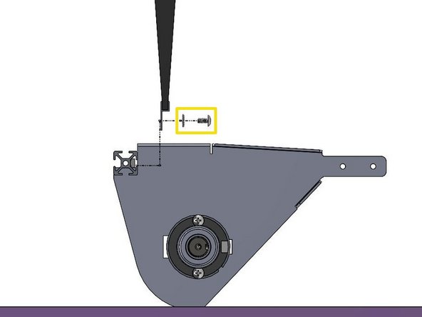
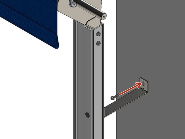
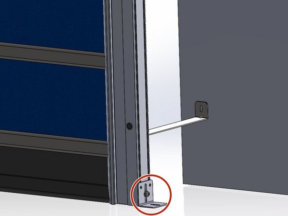
Set the Bracket in place at the bottom of the Vertical Track and make a mark on the Track for a through hole.
-
Drill a clearance hole for the 1/4-20 Machine Screw.
-
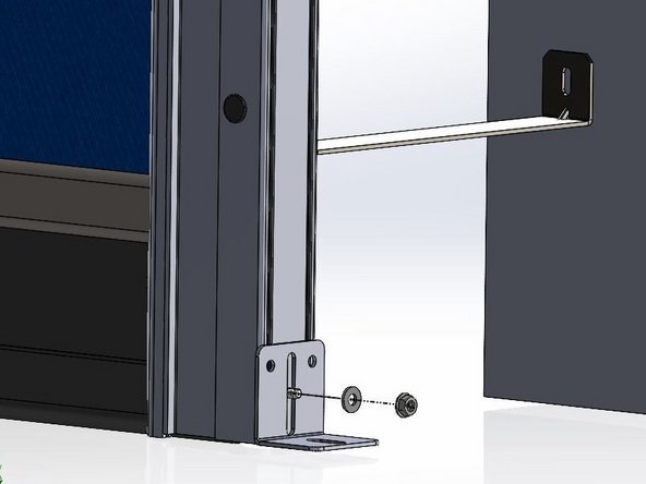
Insert the Machine Screw from the Inside the Vertical Track so that the Threaded end sticks out, allowing the Bracket, Washer, and Flange Nut to be installed on the outside of the Track.
-
-
-
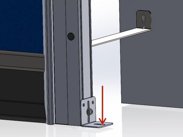
Drill directly through the bottom hole on the bracket into the floor.
-
Fasteners for anchoring into the floor/ground are not provided.
-
Please use best judgment to decide the appropriate fastener for your specific floor material.
-
Repeat on opposite Vertical Track Assembly.
-
Completely tighten all fasteners to ensure Vertical Tracks are wobble-free.
-


Team
