-
-
Technical Support Contacts:
-
Phone: 262-746-3374
-
Email: techsupport@goffscw.com
-
Website: http://www.goffsenterprises.com
-
-
-
The Door Header must be level for the Door to operate properly.
-
Check the door opening Header for level, and adjust the installation accordingly.
-
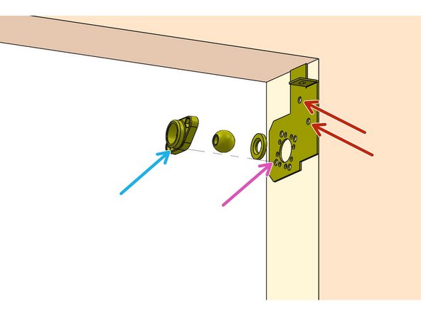
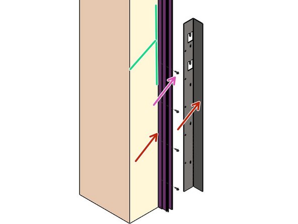
Locate the Left Hand Header Mounting Bracket, and prepare to work on the upper Left of the Door Opening.
-
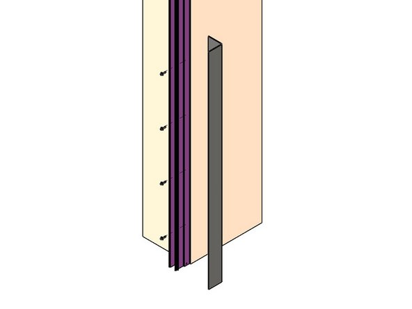
Viewed from Back Surface.
-
Align the top edge of the Bracket to the upper surface of the Door Opening.
-
Align the back edge of the Bracket to the Back Edge of the Door Opening.
-
Measure the Hole Centers on the Bearing Block to help determine which Mounting Holes will be used in the Bracket.
-
Transfer Four Hole locations onto the Mounting Surface.
-
-
-
Prepare the Mounting Surface for Wall Mounting Hardware.
-
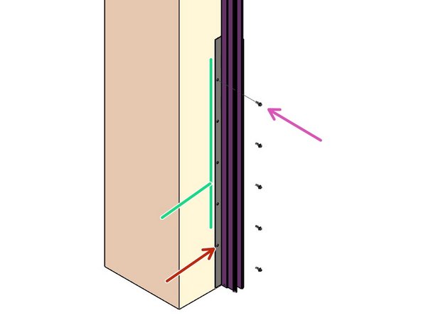
Insert your Wall Mounting Hardware through Idler Bearing assembly (3 pieces).
-
Then through the Left Hand Header Mounting Bracket, into the Mounting Surface.
-
-
-
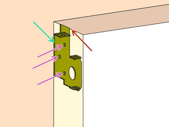
Viewed from Back Surface.
-
The Door Header must be level for the Door to operate properly.
-
Locate the Right Hand Header Mounting Bracket, and prepare to work on the upper Right of the Door Opening.
-
Align the top edge of the Bracket to the upper surface of the Door Opening.
-
Align the back edge of the Bracket to the Back Edge of the Door Opening.
-
Transfer Three Hole locations onto the Mounting Surface.
-
Prepare the Mounting Surface for Mounting Hardware.
-
Mount the Header Mounting Bracket to the Mounting Surface.
-
-
-
Use 2 people, and 2 ladders at minimum.
-
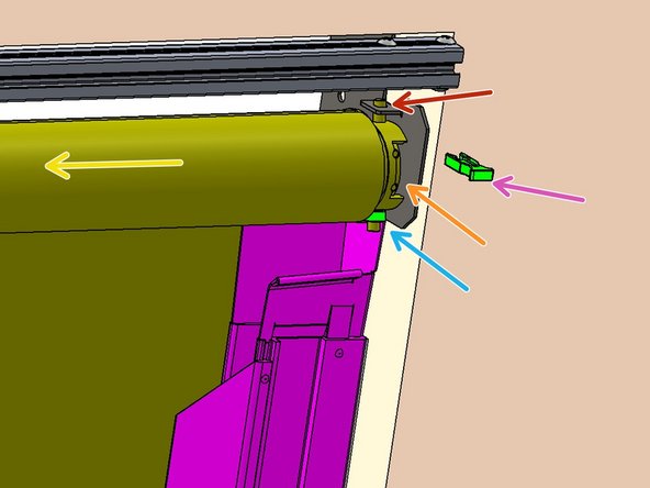
Raise the Header Assembly
-
Insert the Idler Shaft into the installed Idler Bearing Assembly at Upper Left.
-
At the right side, orient the Switches toward the Front.
-
Insert the Upper Motor Peg fully into upper hole of R.H. Header Mounting Bracket.
-
Slip the plastic Ring onto Lower Motor Peg.
-
Insert the Lower Motor Peg into the Lower hole on the Header Mounting Bracket.
-
Insert the plastic Clip onto the Upper Motor Peg to fill space between the Bracket and Motor.
-
-
-
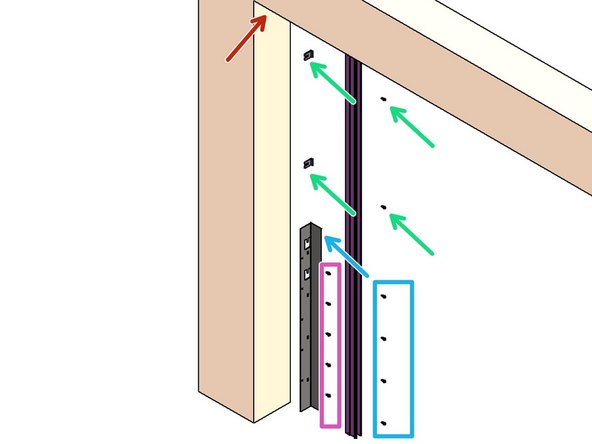
Align Track to the Header Bracket.
-
Transfer and prepare Track Mounting Hole locations.
-
Install Bolts and Spacers in Top two Track holes.
-
Temporarily Install Fall Guard Bracket at Bottom.
-
Install five additional Bolts on Bottom Bracket (outside of Track).
-
Plumb the Track.
-
Securely fasten all hardware.
-
-
-
Use two people to make this process easier.
-
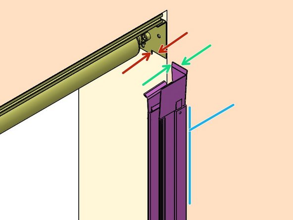
Align the mating surfaces of the Track Transition Bracket -
-
-to the Header Mounting Bracket.
-
Plumb Track Assembly (Front to Back).
-
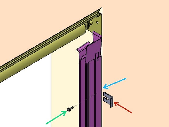
Transfer six Track Mounting Hole locations onto the Mounting Surface.
-
Prepare the Hole locations for the Mounting Hardware.
-
-
-
Move the Track back into place.
-
Partially thread a Bolt through the top hole of the Track into the Mounting Surface.
-
Slide a Spacer-
-
-between the Track and the Mounting Surface to space the Track away from the wall.
-
The Spacer Flange should rest against the Back Surface of the Track.
-
Loosely thread a Bolt in the Second hole from the Top of the Track.
-
Insert a Spacer between the Track and the Mounting Surface at the second Hole.
-
-
-
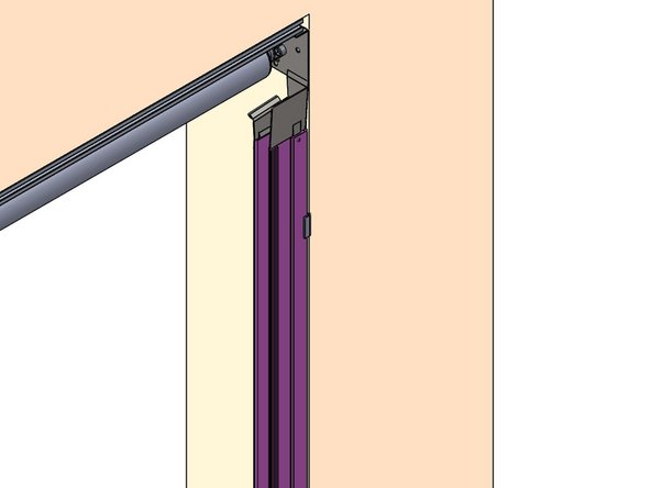
From the Back, slide the Bottom FG Bracket between the Track and the Mounting Surface.
-
The Fall Guard Brackets should be oriented so that the Flange reinforces the Rear of the Track.
-
Loosely thread four Screws through the Track
-
through the Slots of the Fall Guard Bracket
-
into the prepared holes in the Mounting Surface
-
Plumb the Track Front to Back.
-
Ensure that all three Brackets fit tightly against the Back of the Track.
-
Snugly tighten all six Screws.
-
-
-
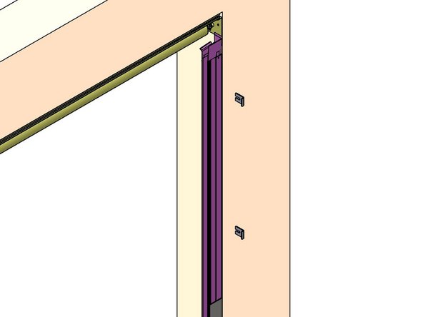
Mark and prepare 5 holes for the Bottom Fall Guard Bracket.
-
Install five Screws through the FG Bracket to the wall.
-
Plumb the Track.
-
Fully tighten all 11 Bolts
-
Repeat for the other Track Assembly
-
Almost done!
Finish Line


