
-
-
Technical Support Contacts:
-
Phone: 262-746-3374
-
Email: techsupport@goffscw.com
-
Website: http://www.goffsenterprises.com
-
-
-
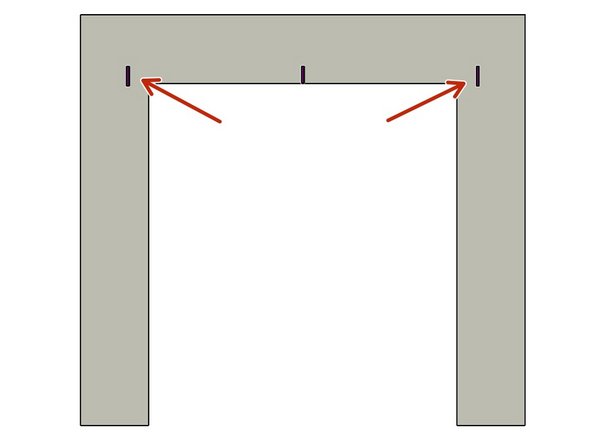
Measure the Opening Width near the top of the Opening.
-
Divide that overall width measurement in half to find the Centerline location.
-
Clearly Mark the Centerline location.
-
-
-
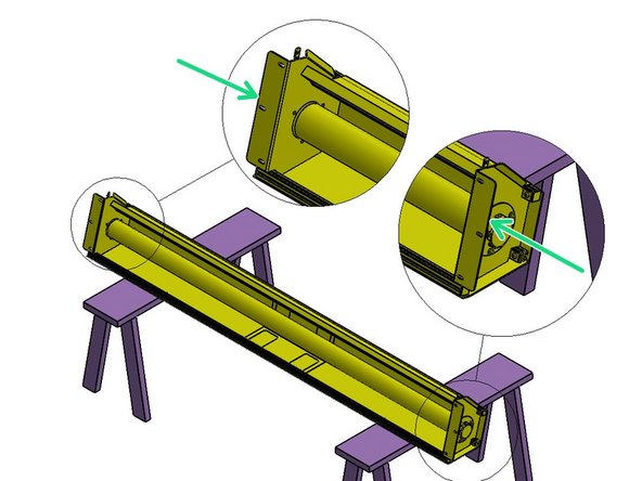
The Header Measuring Process is identical for all Door Models. The Door Model you are installing may be different from the Model shown.
-
Place the Door roll Header Assembly across a safe and level work surface, and rotate the roll assembly frame so that the Header Bracket Mounting flanges are facing upward.
-
Measure the total width of the whole roll assembly from outermost edge of one Header Bracket’s Mounting flange to the outermost edge of the opposite side.
-
Divide that number by 2. This number is 1/2 of the Header Width, and is used to determine the Header location on the Left and Right Sides of the opening.
-
-
-
Mark this dimension on each side of the Opening Center mark.
-
-
-
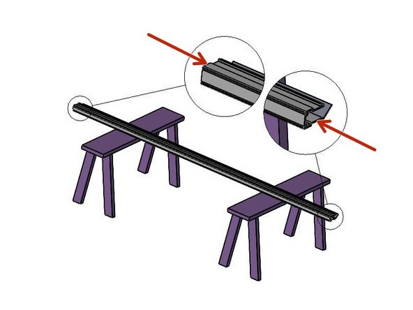
The Track Measuring Process is identical for all G1 Door Models. The Door Model you are installing may be different from the Model shown.
-
Set one of the Vertical Track Assemblies on your work surface.
-
Measure the Length of the Vinyl Track only.
-
ADD 4” to this number and take note.
-
This is the Height dimension needed to mark the location of the Bottom edge of the Header Mounting Brackets.
-
-
-
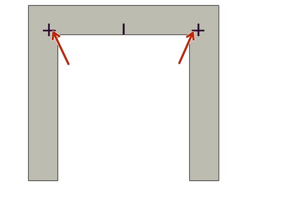
With the Calculated number (Track length + 4"), add a Horizontal line on each side of the Opening that intersects the previously drawn Vertical line.
-
-
-
Use two (2) people, and two ladders (at minimum).
-
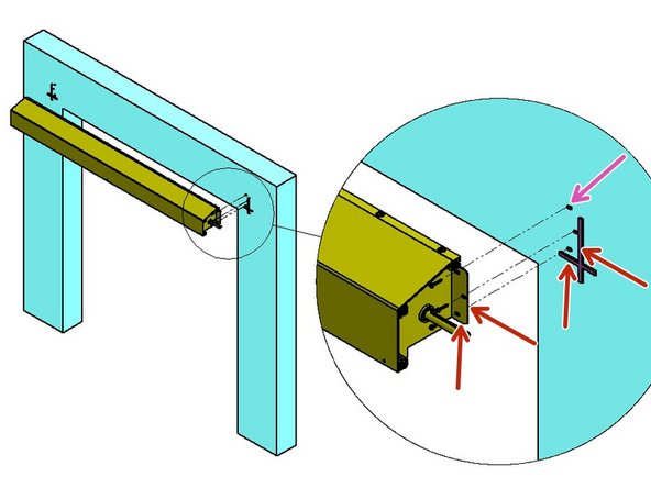
Raise the Roll Header Assembly into place on the wall.
-
The bottom and outside edges of the Header Mounting Brackets should fit inside of Marks on the Mounting Surface.
-
Transfer the (3) Slot locations, per side, onto the Mounting Surface.
-
Prepare the locations for Hardware appropriate to the building material.
-
Loosely secure with three (3) sets of mounting hardware per side.
-
Level the Header Assembly, and fully tighten all six sets of hardware.
-
At this point leave the Door/Web Roll tied off and held in place as it comes.
-
-
-
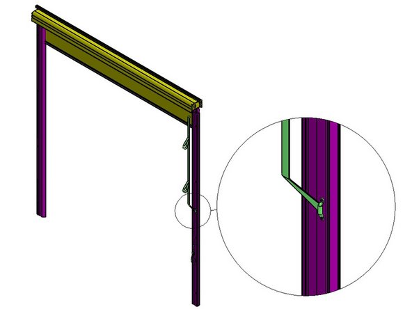
The Track Transition Bracket mounts to the Inside of the tab of the Header Assembly Mounting Bracket.
-
It is important to insert the Carriage Bolt from the inside of the Transition Bracket and the Washer and Hex Nut on the outside of the Header Bracket.
-
The Track must be plumb before securing it to the Mounting Surface.
-
-
-
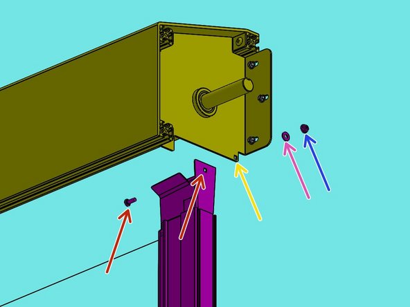
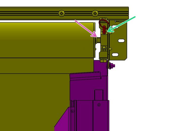
The Track assembly mounts to the Inside of the Header Assembly Mounting Bracket.
-
From the inside of the Track, Insert the Carriage Bolt fully through the Square hole.
-
Move the Track to the Inside of the Header Bracket, then push the Bolt through the Square hole in the Tab.
-
Slide the Washer onto the Bolt from the outside of the Header Bracket.
-
Then snug the Hex Nut on the Bolt.
-
-
-
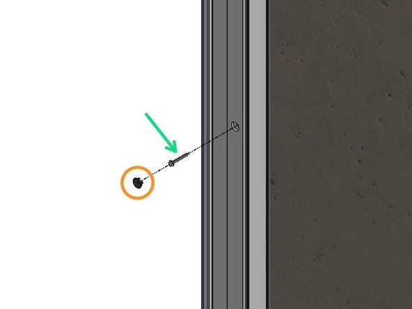
Remove the Black Plastic Plugs from the Track front. These are Mounting access Holes.
-
Use a Level to Plumb the Track and Transfer the Mounting Hole locations onto the Mounting Surface.
-
Remove the Track, and Prepare these locations for Hardware Appropriate to the Building Material.
-
Most Materials will Require Pre-Drilling Holes to Accept the Necessary Hardware.
-
With the Track Assembly Reinstalled and “Hanging” in this position, Plumb the Track to make sure it is Vertically Aligned.
-
Secure the Tracks to the Wall with Hardware Appropriate for your Mounting Surface Material.
-
Replace Plastic Caps.
-
-
-
The top edge of the second lowest Wind Bar of the Door will be where the Lock Pin meets and holds the Door in the closed position. A factory-cut notch is located in the Door Panel, on the right-hand side, to allow the Lock Pin to pass through the Door.
-
Using the Pull Strap, pull the Door down/closed until a satisfactory seal with the floor is achieved.
-
Mark the location of the top edge of the second lowest Wind Bar onto the Right-Hand Door Track.
-
Release the Pull Strap to allow the door to return to the Open Position.
-
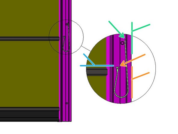
Drill a ¼” Dia. hole through both legs of the track 2” from the right (outside of the track) which intersects your line.
-
Drill a 3/16” hole, a few inches above the ¼” hole, at about ¾” from the right (outside of the Track).
-
Insert the Lanyard/cord through this hole, and tie a knot on that end.
-
To hold the Door in the Closed position: Pull the Door down to the closed position, and insert the Lock-Pin above the Wind Bar through the front and rear holes of the Door Track.
-
-
-
With the Door in the Open Position:
-
Pull the loose end of the long Strap through the Tie-off Bracket attached to the Right-Side Door Track.
-
Use the Buckle provided to secure the long Pull Strap to the loose end
-
Adjust the length to set the upper Stop Point of the Door.
-
-
-
Raise the Door to the fully Open position. This Unloads much, but NOT all, of the Spring Loading.
-
To fully Unload the Spring, with the Door raised, pull the Pin. The Shaft may spin inside as the Spring fully unloads.
-
Secure the Door Webbing to the Roll Tube to hold it in place during this process.
-
-
-
Spring tension is maintained either with a ½” open-end wrench on the wrench flats, or with the Quick-Release pin.
-
Spring tension is increased/decreased with a two-step process.
-
To increase spring tension, insert the open-end wrench onto the wrench flats and hold firmly
-
then pull the Quick-Release pin.
-
Pull the wrench down (CCW) until the pin can be replaced – about a quarter turn.
-
Repeat this two-step process about 8 times equaling about 2 full turns on the spring.
-
Release the ties on the Door Roll Assembly.
-
-
-
Pull the Door fully Closed, then release the Strap.
-
Note the Opening Stop Point.
-
Adjust the Opening Stop Point by increasing/decreasing the tension 1 quarter turn.
-
Test and adjust as needed.
-


Team
