
-
-
Technical Support Contacts:
-
Phone: 262-746-3374
-
Email: techsupport@goffscw.com
-
Website: http://www.goffsenterprises.com
-
-
-
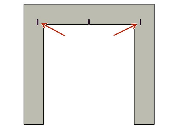
Measure the Opening Width near the top of the Opening.
-
Divide that overall width measurement in half to find the Centerline location.
-
Clearly Mark the Centerline location.
-
-
-
The Header Measuring Process is identical for all Door Models. The Door Model you are installing may be different from the Model shown.
-
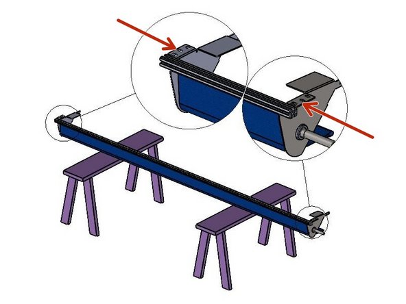
Place the Door roll Header Assembly across a safe and level work surface, and rotate the roll assembly frame so that the Header Bracket Mounting flanges are facing upward.
-
Measure the total width of the whole roll assembly from outermost edge of one Header Bracket’s Mounting flange to the outermost edge of the opposite side.
-
Divide that number by 2. This number is 1/2 of the Header Width, and is used to determine the Header location on the Left and Right Sides of the opening.
-
-
-
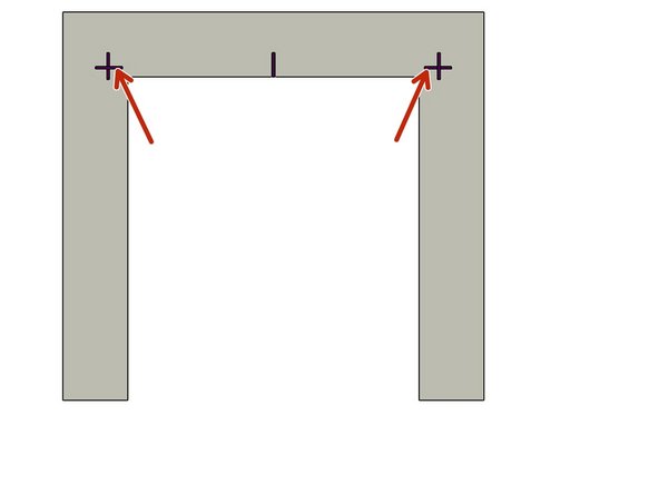
Mark this dimension on each side of the Opening Center mark.
-
-
-
The Track Measuring Process is identical for all G1 Door Models. The Door Model you are installing may be different from the Model shown.
-
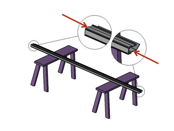
Set one of the Vertical Track Assemblies on your work surface.
-
Measure the Length of the Vinyl Track only.
-
ADD 5-3/4” to this number and take note.
-
This is the Height dimension needed to mark the location of the Bottom edge of the Header Mounting Brackets.
-
-
-
With the Calculated number (Track length + 5-3/4"), add a Horizontal line on each side of the Opening that intersects the previously drawn Vertical line.
-
-
-
Use two (2) people, and two ladders (at minimum).
-
Raise the Roll Header Assembly into place on the wall.
-
The Bottom and Outside edges of the Header Bracket Mounting Flanges should fit inside of Marks on the Mounting Surface.
-
Transfer the (3) Slot locations, per side, onto the Mounting Surface.
-
Prepare the locations for Hardware appropriate to the building material.
-
Loosely secure with three (3) sets of mounting hardware per side.
-
Level the Header Assembly, and fully tighten all six sets of hardware.
-
At this point leave the Door/Web Roll tied off and held in place as it comes.
-
-
-
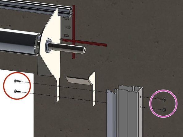
The Track Transition Bracket mounts to the Inside of the tab of the Header Assembly Mounting Bracket.
-
It is important to insert the Carriage Bolt from the inside of the Transition Bracket and the Washer and Hex Nut on the outside of the Header Bracket.
-
The Track must be plumb before securing it to the Mounting Surface.
-
-
-
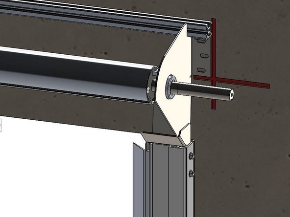
The Track Assembly Mounts to the Outside of the Header Mounting Bracket, with the Transition Bracket Sandwiched in the Middle.
-
Insert the (2) Carriage Bolts so that they pass through the Holes in the Header Mounting Bracket, Transition Bracket, and Vertical Track Assembly.
-
Then snug the Hex Nut on the Bolt from the Outside.
-
-
-
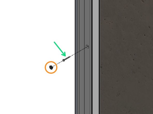
Remove the Black Plastic Plugs from the Track front. These are Mounting access Holes.
-
Use a Level to Plumb the Track and Transfer the Mounting Hole locations onto the Mounting Surface.
-
Remove the Track, and Prepare these locations for Hardware Appropriate to the Building Material.
-
Most Materials will Require Pre-Drilling Holes to Accept the Necessary Hardware.
-
With the Track Assembly Reinstalled and “Hanging” in this position, Plumb the Track to make sure it is Vertically Aligned.
-
Secure the Tracks to the Wall with Hardware Appropriate for your Mounting Surface Material.
-
Replace Plastic Caps.
-


Team
