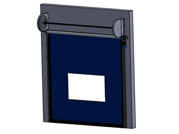
-
-
Scan this QR code to view our installation video on YouTube.
-
USE THE VIDEO AS A SUPPLEMENT TO THE MANUAL... THE VIDEO IS LACKING IMPORTANT DETAILS PERTAINING TO THE INSTALL PROCEDURE.
-
-
-
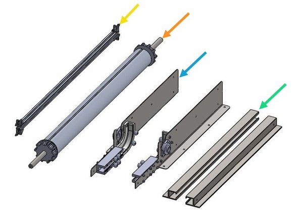
When your door arrives, it will be in a wooden crate. Please locate and identify the following components:
-
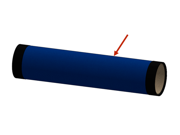
Curtain Assembly (Leave rolled and shrink wrapped on the cardboard core for the installation).
-
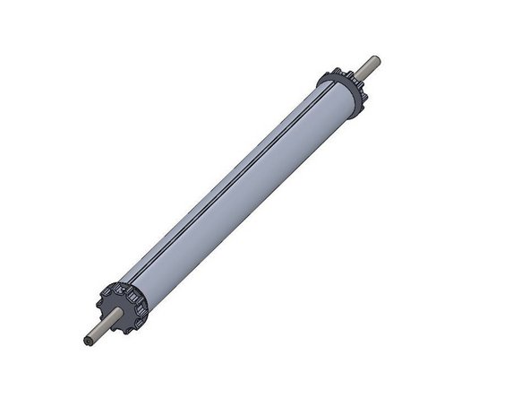
Roll Tube Assembly with Drive Shafts
-
Spiral Stabilizer Bar Assembly
-
(1) Left and (1) Right Vertical Track Assemblies
-
(1) Left and (1) Right Header Side Plate Assemblies
-
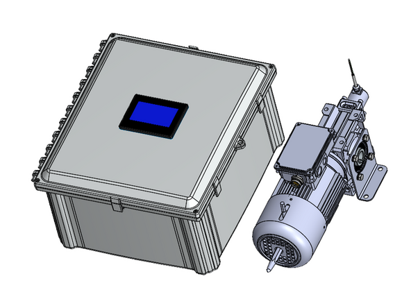
Motor and Control Panel (each in their own box)
-
-
-
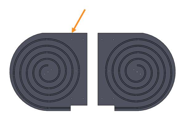
(1) Left and (1) Right Spiral Header
-
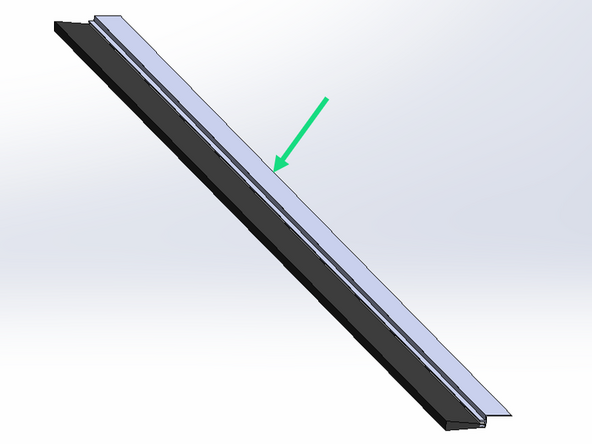
(1) Door Jamb/Lintel Brush Seal
-
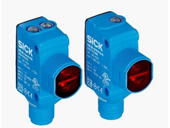
(1) Set of Through-Beam Photo Eyes (at minimum)
-
-
-
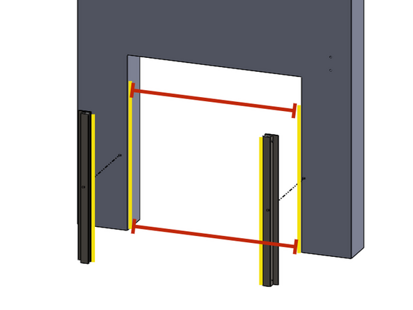
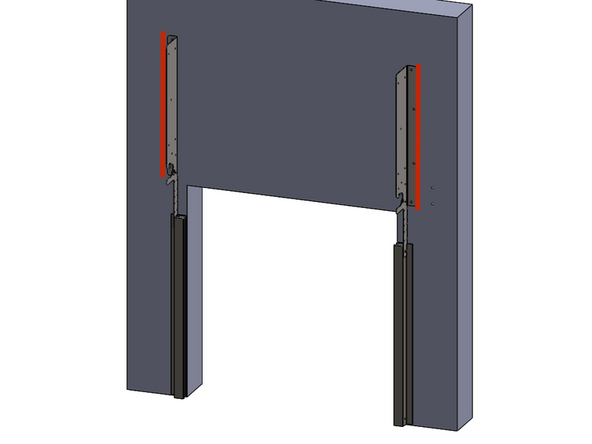
The inner edges of the vertical tracks should mount flush with the vertical edges of the opening (assuming door jambs are plumb).
-
While mounting the tracks on the wall, measure the distance between the left and right vertical tracks, at the top and bottom, and make sure those measurements match the opening width called out on the order.
-
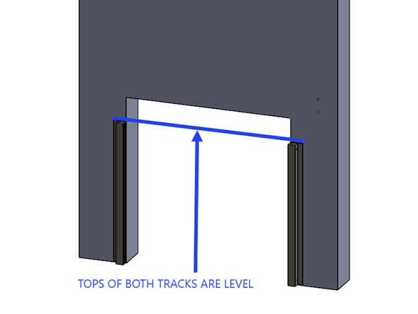
It is imperative that the top of each vertical track is at the same elevation above the floor to ensure the curtain travels true.
-
Uneven floors can effect the curtains alignment if the tops of the tracks are not level with each other.
-
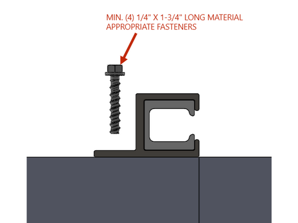
At a minimum, use (Qty 4) 1/4" x 1-3/4" long material appropriate fasteners in the mounting tab of each vertical track.
-
Once installed, ensure the tracks are plumb.
-
Measure the distance between the tops of both tracks, and the bottom of both tracks. These measurements should be the same (tracks are plumb), and should match opening width callout on order.
-
Do not trust that the door jambs are perfectly plumb.
-
-
-
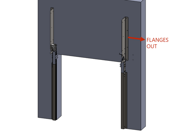
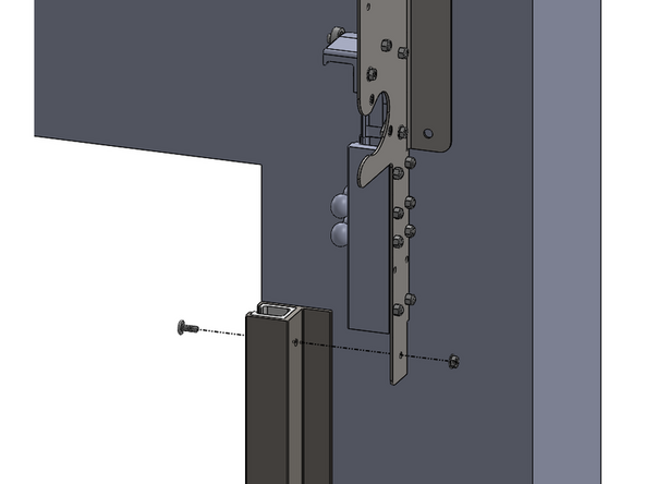
Using the carriage bolt assembly installed in the top of each vertical track, mount the side plate assemblies to the tracks.
-
Ensure the side plate mount flanges are going outward.
-
-
-
Ensure the side plate mounting flanges are plumb before securing them into the mounting surface.
-
This is important to ensure there is no binding as the curtain feeds through the spirals.
-
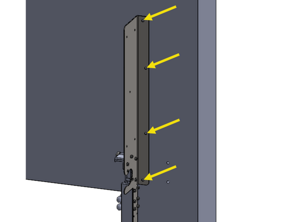
Each side plate has (4) mounting holes that will accommodate up to 3/8in material appropriate fasteners.
-
-
-
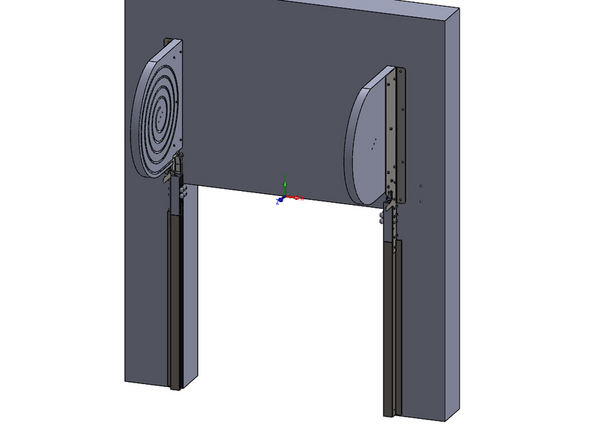
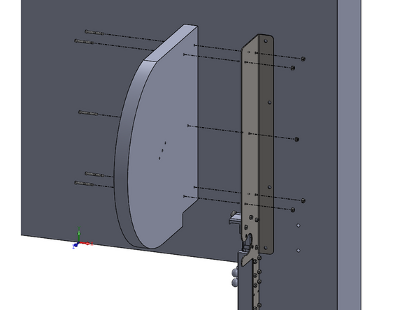
Each spiral mounts with (5) 1/4-20 x 2.125in long shoulder bolts and 1/4-20 nylon-insert lock nuts.
-
The bolts can be installed with a 1/8in Allen wrench.
-
The nuts can be held used a 7/16in wrench or socket.
-
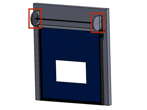
The spiral raceways face inwards towards each other.
-
-
-
Goff's REQUIRES lubrication of the spirals during the original installation, and any time the curtain is replaced. This will ease the stress on the system before the wear components are broken-in and become self-lubricating.
-
If lubrication is not allowed due to the application, the grease can be cleaned/removed after the curtain assembly is completely installed.
-
Though not required throughout the entire life of the door, Goff's recommends keeping the door spirals lubricated in order to minimize friction and wear on the door system. This will maximize the life of the door curtain and motor, while preventing unnecessary downtime and repairs.
-
Goff's will provide a tube of the recommended grease. We use Super Lube Multipurpose Food Grade Synthetic Grease (Mfr. Part No. 41150).
-
This process is easiest with any industrial/heavy-duty grease gun.
-
-
-
Over time, the grease may attract and trap debris from the environment, and it may be necessary to clean/remove this buildup before adding new grease.
-
This can be done with a combination of compressed air, and/or a shop rag and some isopropyl alcohol.
-
Be sure to check the spirals and the vertical tracks for excessive buildup.
-
-
-
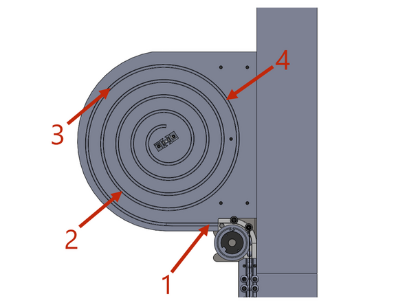
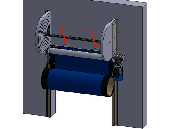
Goff's recommends adding lubrication to the 4 locations see in image 1. These are high friction locations that all doors (regardless of size) will pass during each cycle.
-
Give a couple of squeezes on the grease gun trigger to apply a 2-3in long bead of grease in the spiral pathway at each location.
-
Make sure the grease is getting deep into the spiral pathway/channel.
-
As the door begins cycling again, it will pick up and distribute the grease as needed.
-
Goff's recommends reapplying grease (application dependent) every 20,000-30,000 cycles, or every 3 months (whichever happens first), to maintain optimal friction tolerance, and to maximize the life of the system.
-
-
-
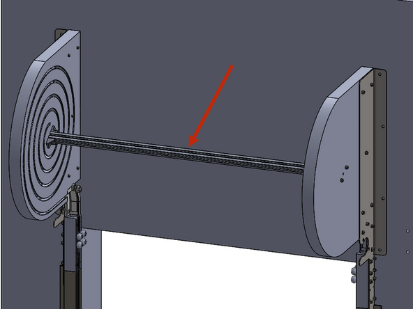
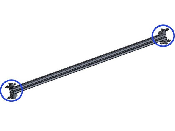
The spiral stabilizer bar anchors the spirals to each other, and keeps them from oscillating during the doors' operation.
-
The spiral stabilizer bar will come pre-assembled.
-
You will need to remove the (4) nuts and (4) bolts out of the ends, to use for its installation.
-
-
-
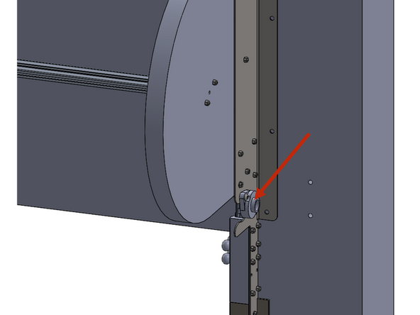
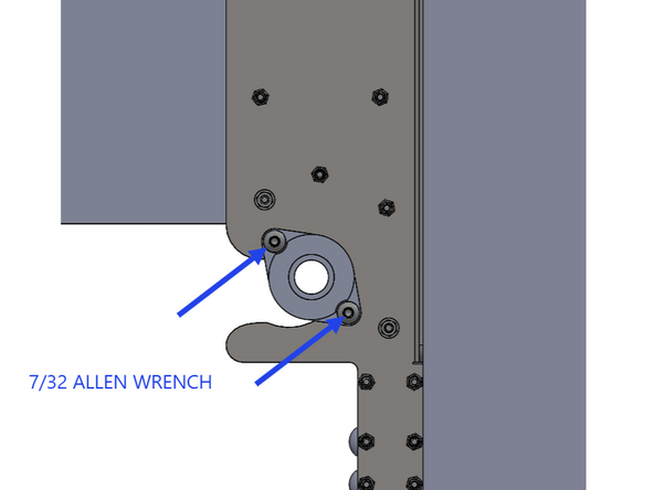
Remove the (2) flange bearings. There will be one on each side of the door.
-
Each bearing is held in place with (2) 3/8-16 x 3/4in long button head screws.
-
To remove the button head screws, use a 7/32 Allen wrench.
-
Set the bearings aside for a later step.
-
-
-
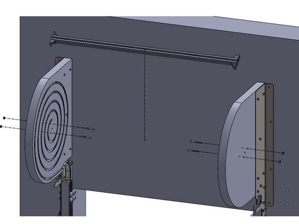
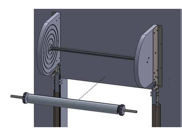
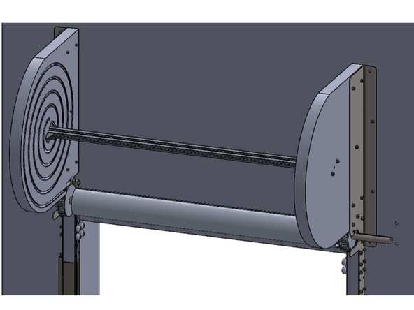
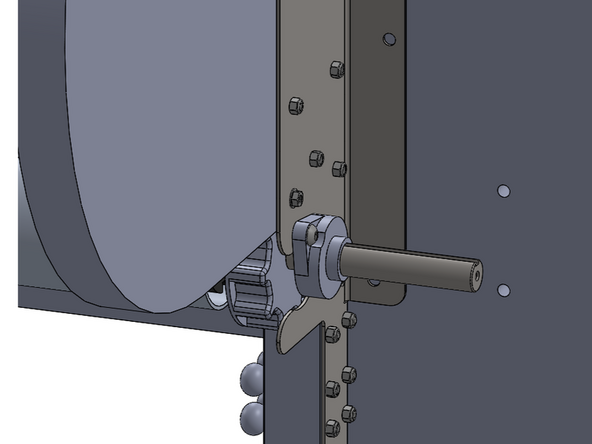
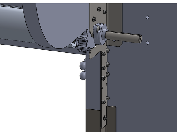
Install the drive tube assembly into the slots in the header side plates.
-
The drive gears on either end of the tube assembly will be inside of the side plates.
-
-
-
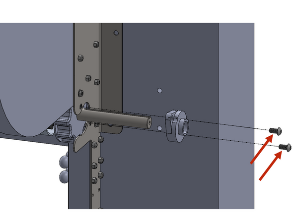
Install the (2) flange bearings onto the exposed drive shafts. There will be one on each side of the door.
-
Each bearing is held in place with (2) 3/8-16 x 3/4in long button head screws.
-
To install the button head screws, use a 7/32 Allen wrench.
-
-
-
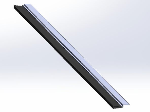
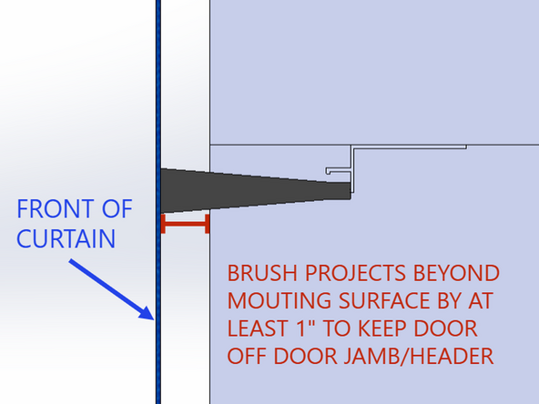
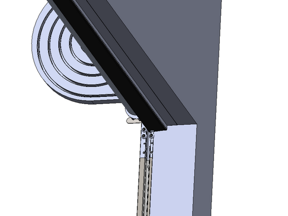
Goff's will supply, (1) lintel brush seal assembly. This keeps the back of the curtain from rubbing on the door jamb/header. It also adds to the perimeter sealing properties of the door.
-
The brush assembly should be centered in the underside of the door jamb/header and should stick beyond the mounting surface of the wall by at least 1in.
-
The brush retainer will be pre-punched will holes to accommodate up to 1/4in material appropriate fasteners.
-
-
-
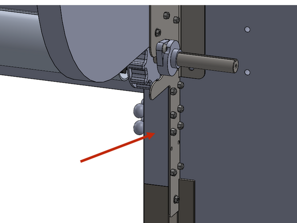
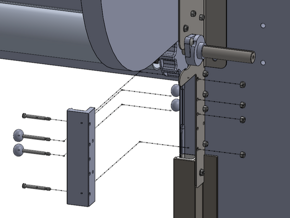
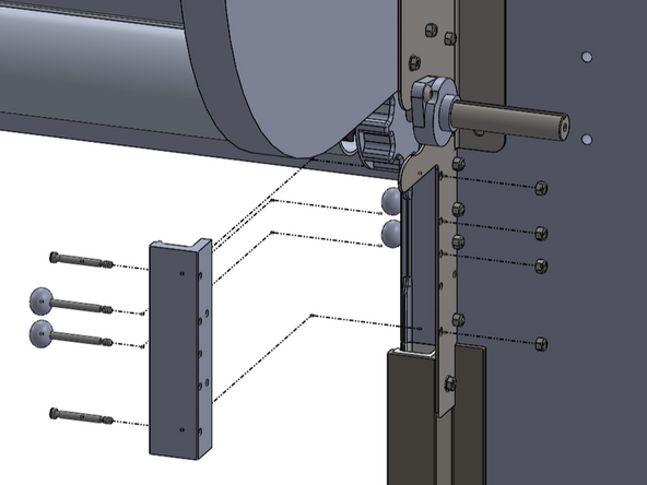
Remove the front-half of the refeed assemblies on both the left and right side of the door.
-
Each one is held in place with (4) 1/4-20 shoulder bolts and nylon-insert lock nuts.
-
The bolts can be removed with a 1/8in Allen wrench.
-
The nuts can be held used a 7/16in wrench or socket.
-
Your refeed assemblies may not have the nylon balls in the lower 2 positions (as shown).
-
Set these parts aside to be reinstalled after the door curtain has been installed.
-
-
-
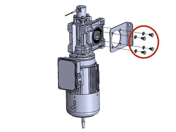
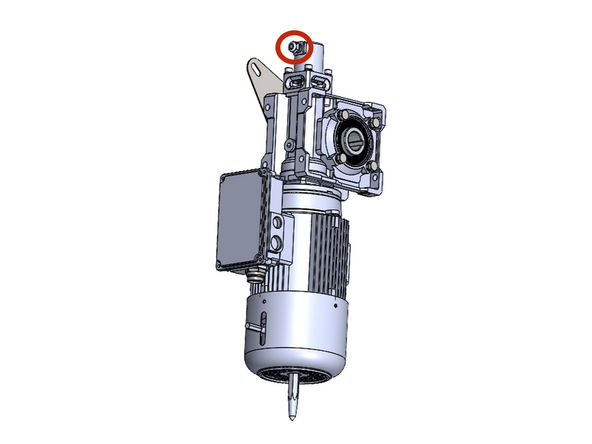
In the box with the motor, thee will be (4) M8x1.25mm x 12mm long hex head bolts and (4) split-lock washers.
-
To install the hex head bolts, use a 1/2in socket or wrench.
-
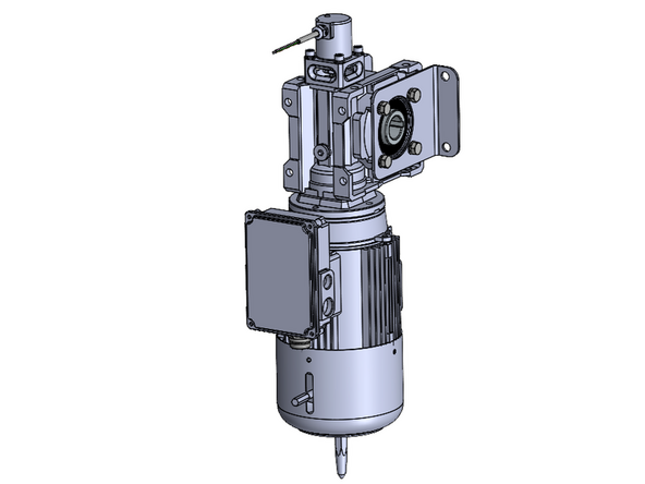
These will be used to secure the anti-torque bracket onto the motor.
-
The bracket goes on the outside of the motor, so if you have a right-hand drive door, the bracket goes on the right side of the motor.
-
-
-
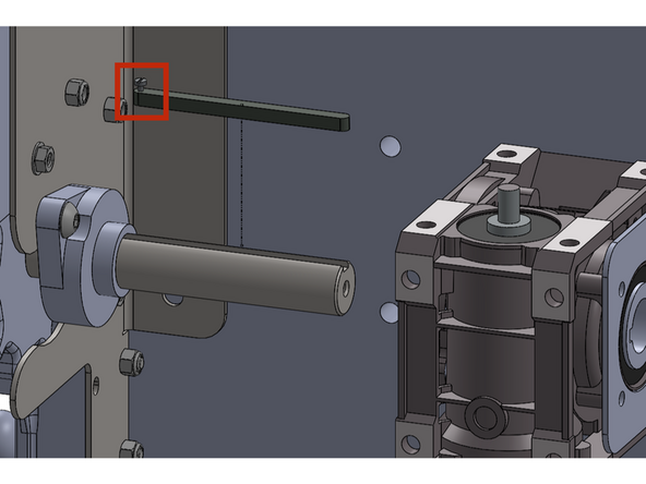
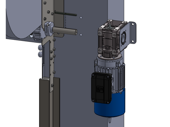
Next, install the motor and machine key onto the drive shaft.
-
The machine key needs to be oriented such that the set screw is between the motor and the door header/side plate. This ensures the machine key cannot fall out.
-
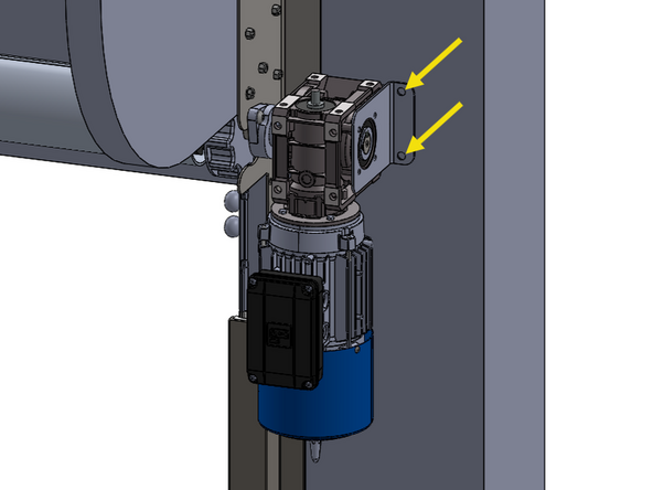
Once the machine key is oriented properly, slide the motor onto the shaft until the end of the shaft is flush with the outside of the motor.
-
Tighten the machine key set screw after the motor is installed.
-
The anti-torque bracket will anchor into the wall/mounting surface via (2) holes that will accommodate up to 3/8in material appropriate fasteners.
-
-
-
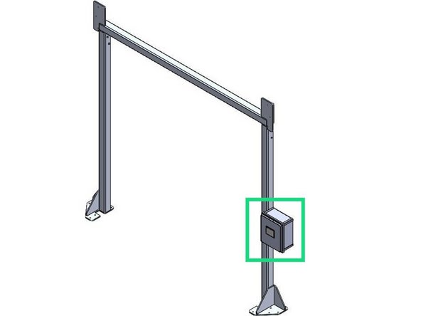
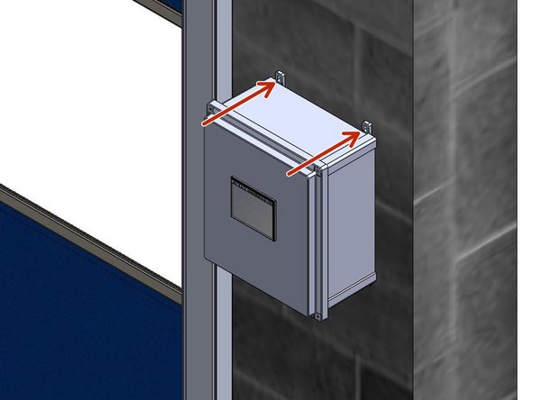
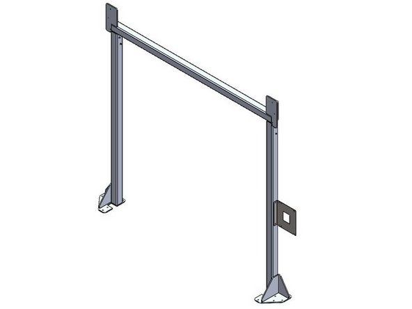
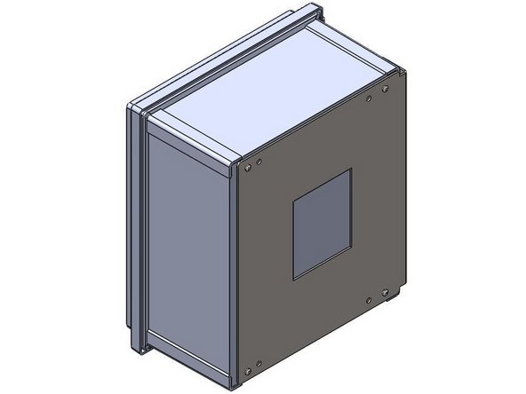
The Goff's Control Panel can be Mounted in two different ways:
-
Flush Mounted on a Wall/Surface with the provided Feet.
-
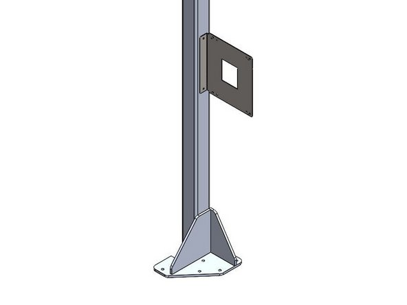
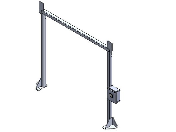
Mounted on a Door Frame with the provided Side-Mount Bracket.
-
Side-Mount Bracket only included when your door is ordered with a Door Frame.
-
-
-
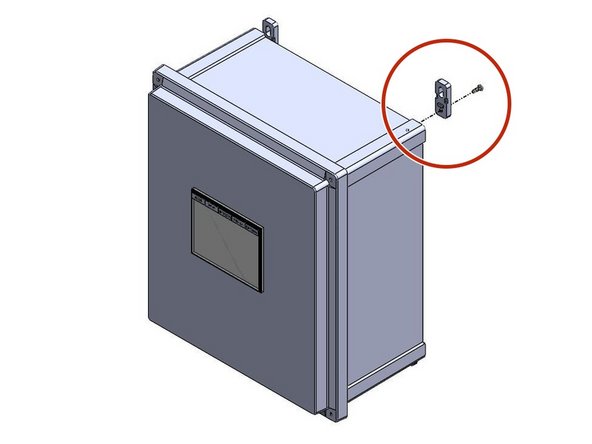
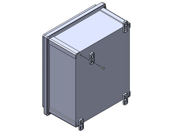
Inside of the Goff's provided Control Panel, there will be a bag containing (4) Feet and (4) 10-32 x 1/2in Screws
-
There are (4) threaded inserts in the back of the Control Panel that will receive the 10-32 x 1/2in Screws.
-
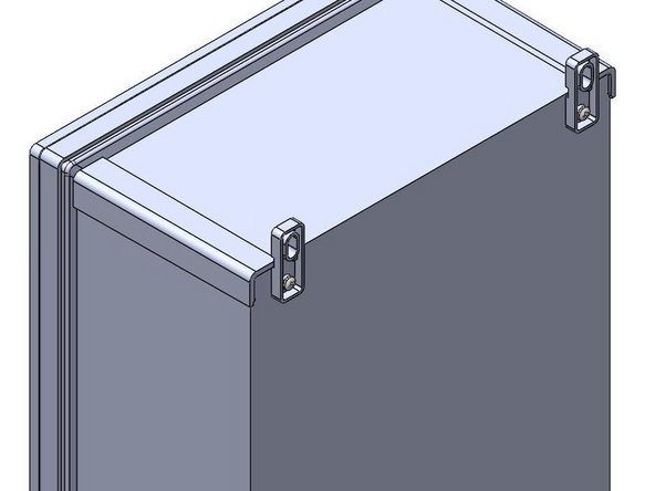
Use these threaded inserts, to Fasten the provided Feet onto the Control Panel.
-
-
-
Goff's does not provide fasteners for your mounting surface. It is up to you to determine the appropriate fasteners for the material you are mounting to.
-
With the appropriate fasteners, secure the control panel to the wall through the feet.
-
The Control Panel can be Mounted at any Height or Location as long as the pre-wired cable can reach the motor.
-
-
-
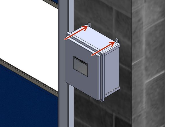
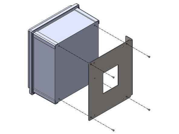
When side-mounting a control panel onto a door frame, the bracket must be mounted to the door frame before the control panel can be mounted to the bracket.
-
Goff's will provide (2) self-drilling fasteners to use for mounting the bracket to the door frame.
-
The bracket/control panel can be mounted at any location on the door frame as long as the pre-wired cable can reach the motor.
-
The bracket can be flipped to allow left- or right-hand mounting.
-
-
-
Inside of the control panel, there will be a bag containing (4) 10-32 x 1/2in screws and (4) feet. We will not use the feet for this type of mounting.
-
The (4) screws will be needed to install the control panel onto the side-mount bracket.
-
There are (4) threaded inserts in the back of the control panel that will receive the 10-32 x 1/2in screws.
-
-
-
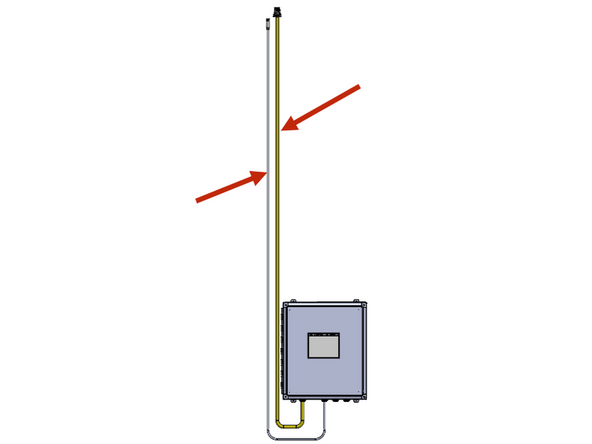
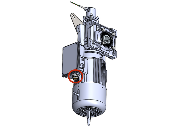
From the Factory, your Goff's Supplied Control Panel will have (2) Cables coming out of it. The yellow cable is for the motor, and the other smaller cable is for the encoder. These cables are equipped with quick-connect threaded plugs that will thread into a receptacle on the motor and encoder.
-
Both cables are 15ft long. Make sure to mount the panel in a location where the cable can reach the motor.
-
If you need to shorten this cable, do it from the end terminated inside the control panel.
-
If you need a longer cable for any reason, Goff's can provide it, but you will lose the quick-connect capability between the motor and panel. This means the panel will need to be hard-wired into the motor in the field.
-
Make the connections at the motor and encoder.
-
It is critical to keep the high voltage motor cable, and the low voltage encoder cable separated and not tied together.
-
-
-
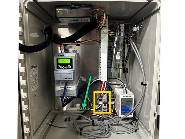
Open the control panel.
-
Route the power supply wires into the control panel via the provided entry points on the bottom of the enclosure.
-
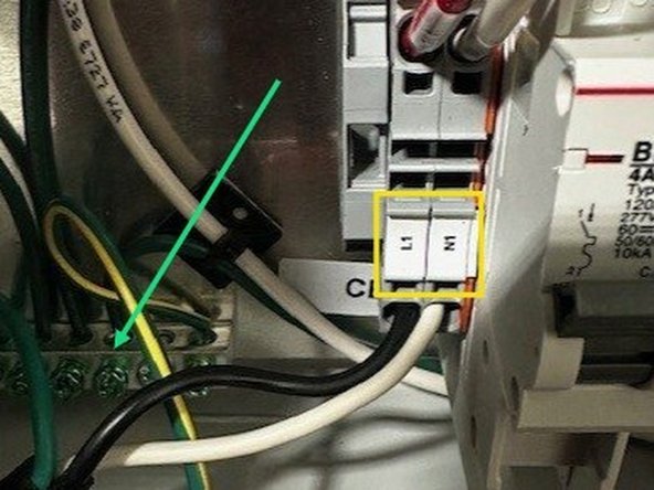
Locate the incoming power terminal block in the lower portion on the control panel. Make the appropriate connections.
-
L1
-
N: Single Phase ONLY
-
L2: 3-Phase ONLY
-
L3: 3-Phase ONLY
-
Grounding Bar
-
-
-
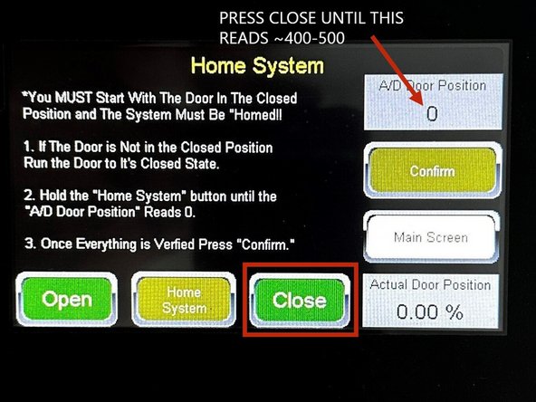
Press the following sequence of buttons to get to the limit setting screen(s):
-
Setup & Diagnostics
-
Setup
-
Quick Setup
-
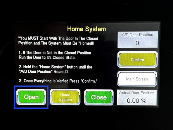
BEFORE PROCEEDING TO LOAD THE CURTAIN, USE THE CLOSE BUTTON ON THIS SCREEN TO ROTATE THE DRIVE TUBE UNITL THE A/D DOOR POSITION VALUE READS ~400-500.
-
The buttons on the limit setting screen are "dead-man" switches; they only move the door while they are being held.
-
-
-
Click here to watch a video of the curtain installation procedure.
-
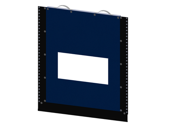
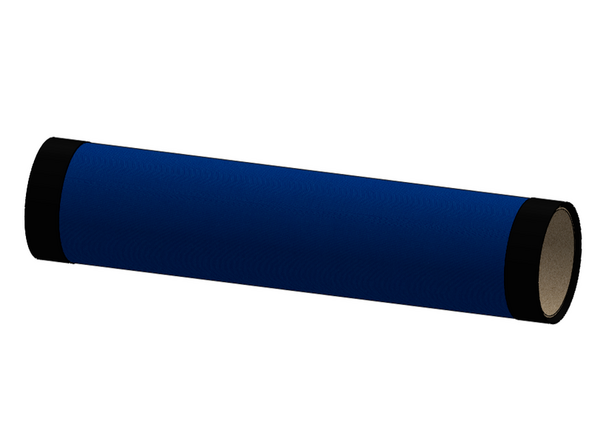
The curtain assembly will arrive rolled up around a cardboard core.
-
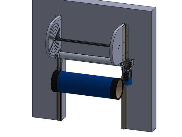
Leave it rolled up on the cardboard core during the curtain installation, as this will make it easier to handle and lift with a forklift if applicable.
-
-
-
This portion of the installation will take at minimum, 3 people.
-
There are two ways to get the curtain assembly lifted into place for installation:
-
Scissor lift
-
Forklift
-
If using a Forklift, it will be necessary to also have ladders or a man-lift for 2 people to be up near the header (both sides) to load the curtain into the drive gear.
-
While the curtain assembly is still rolled up, center the roll in front of the opening and lift the curtain assembly up near the top of the opening.
-
If using a forklift, it is easiest if the forklift lifts the roll, and approaches from the backside of the opening, while the ladders and/or man-lift are in front of the door/opening.
-
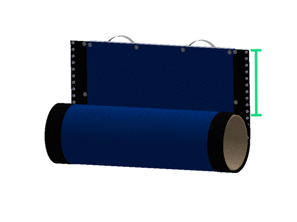
Once the roll is in place near the top of the opening, unroll the top 2-3 feet of the curtain off the roll.
-
-
-
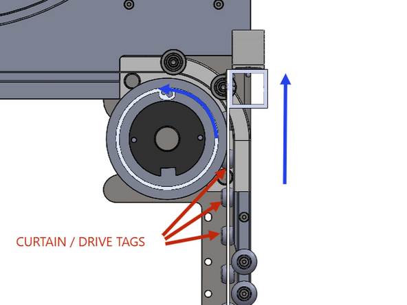
Using the grab-handles on the leading edge of the curtain assembly, pull the curtain up and into the drive gears, through the opening in the front of the tracks, so that the curtain is behind the roll tube.
-
IT IS IMPERATIVE THAT THE FIRST RETENTION TAB ON THE LEFT AND RIGHT SIDE OF THE CURTAIN GETS GRABBED BY THE DRIVE GEARS AT THE SAME TIME TO ENSURE PROPER TIMING.
-
While the curtain is being pulled up into the drive gear, someone will need to give a short press of the Open button on the limit setting screen (SETUP & DIAGNOTICS > SETUP > QUICK SETUP). This will turn the roll-tube a few inches, and pull the first few retention tabs into the drive gear.
-
The buttons on the limit setting screen are "dead-man" switches; they only move the door while they are being held.
-
If the curtain does not feed into the drive gear evenly, use the close button to lower the curtain out of the drive gear, and try again.
-
Before loading the curtain all the way up into the spirals, it is critical to make sure the curtain is timed properly.
-
Once the curtain is timed properly, continue to press the open button until the curtain is loaded completely into the spirals. STOP WHEN THE BOTTOM OF THE CURTAIN REACHES THE REFEED ROLLERS. ENSURE THE WIRELESS TRANSMITTER IS A FEW INCHES BELOW FROM THE ROLL TUBE.
-
-
-
Replace the front-half of the refeed assemblies (removed in step 10) on both the left and right side of the door.
-
Each one is held in place with (4) 1/4-20 bolts and nylon-insert lock nuts.
-
The bolts can be installed with a 1/8in Allen wrench.
-
The nuts can be held used a 7/16in wrench or socket.
-
Your refeed assemblies may not have the nylon balls on the middle two bolts.
-
-
-
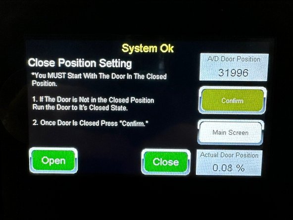
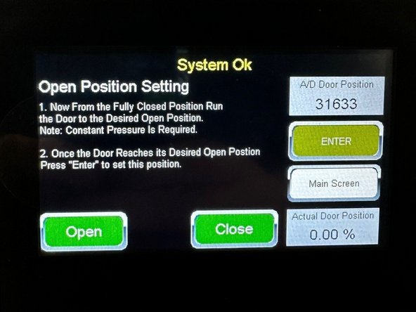
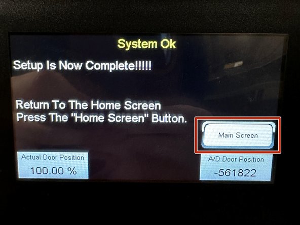
Once the curtain assembly is loaded into the drive gears and timed, follow the on-screen procedure to set the open and closed limit positions.
-
Once complete, tap the "Main Screen" Button to return to the home screen. Your door is now ready to operate.
-
-
-
After setting the limits, you may notice that the door isn't traveling to the fully open and/or close positions as we just set them.
-
As a safety feature to ensure the door doesn't overtravel during setup, we set the full open and close positions short of where you just taught them (98% and 2%, respectively).
-
Theoretically, the open position we taught in the previous step is 100%, and the close is 0%.
-
Cycle the door a few times to ensure the current limit positions are repeatable before making any of the following adjustments... If we move the limits to the final positions (100% and 0%), and the door over travels slightly, we risk the curtain getting damaged.
-
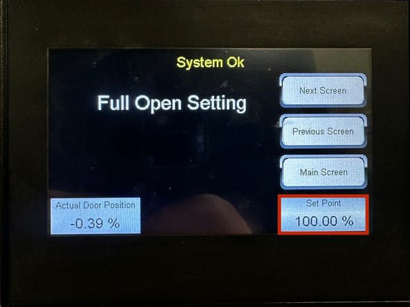
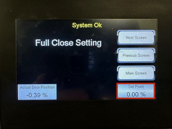
Once confirmed, from the Operator Screen, Press: SETUP & DIAGNOSTICS > Setup > Settings > Next Screen > Door Positioning
-
Tap in the Set Point box and gradually adjust the "Full Open" (first screen) and "Full Close" (press Next Screen button) Settings until the door comes to a full stop at your desired limit positions.
-
The third and fourth screens (continue pressing Next Screen) are the Open and Close Slow Down Settings. These allow you to tune the doors slow down/stop curve for the open and close strokes. Make small adjustments as needed and test them each time.
-
Press: Main Screen > Operator Screen at any time to return home.
-
-
-
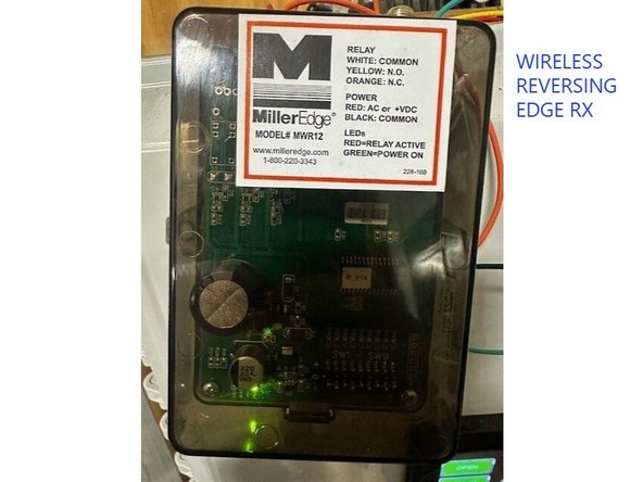
The wireless reversing edge system will be installed and setup from the factory, but it is critical to check that it is working properly before releasing the door for use.
-
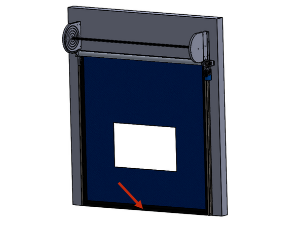
The soft reversing edge will be installed in the pocket on the bottom of the door curtain from the factory.
-
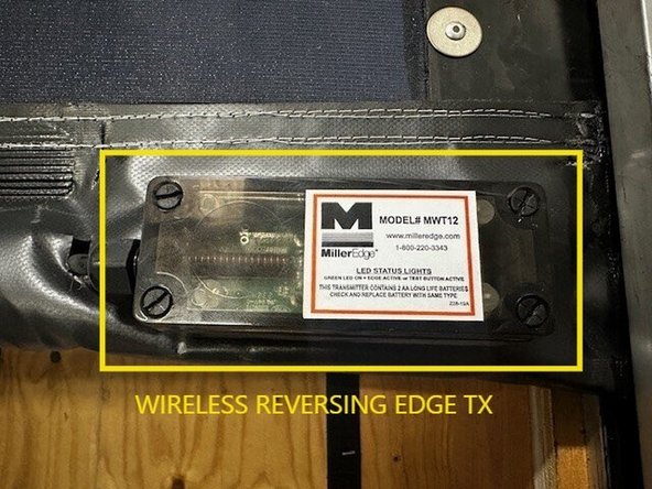
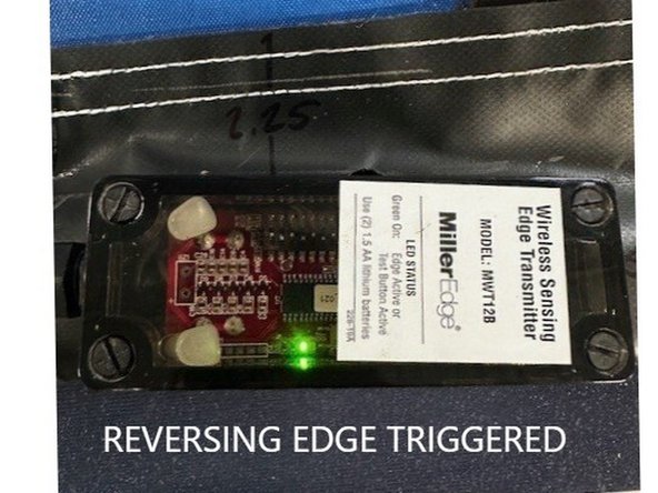
The wireless transmitter will be installed on the outside of the pocket on the bottom of the door curtain from the factory.
-
The wireless receiver will be mounted and wired inside the control panel from the factory.
-
-
-
The door comes equipped with a primary set of safety eyes (through-beam or light-curtains), so the reversing edge is a second layer of safety/redundancy.
-
When the edge is triggered during a close stroke, the door will stop, pause for 2 seconds, and then reverse/open slowly (to the fully open position).
-
If the door is stopped, or is fully closed when the edge is triggered, the subsequent open stroke will be a slow one. The door will return to normal operational speed after returning to the fully open position.
-
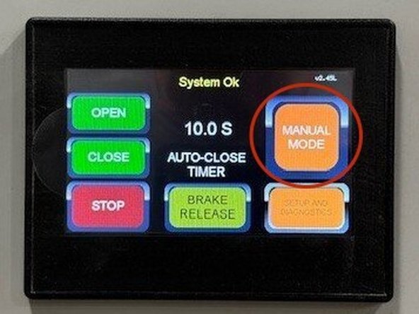
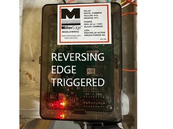
To confirm reversing edge functionality, place the door in manual mode, jog the door a few feet up from the floor and squeeze/compress the bottom pocket. Confirm the green LED on the wireless transmitter illuminates, AND that the touch screen reads "Reversing Safety Edge" while the pocket is compressed.
-
Inside the control panel, a red LED will illuminate on the reversing edges wireless receiver. This confirms the wireless transmitter and receiver are communicating properly.
-
Once these things are confirmed, run a close stroke, and let the door come into contact with something to ensure the edge reverses the door as explained above.
-
-
-
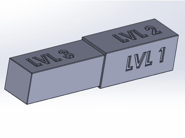
With each Cyclone door, Goff's will provide a track retention adjustment gauge. This will be used to ensure consistent gapping of the vertical track mouth along the entire length of the tracks.
-
There are 3 levels are track retention. The smaller the gap in the track mouth (higher level of retention), the higher the force required to break the door curtain out of the vertical tracks.
-
Level 1: 0.53" Gapping (Lowest Retention)
-
Level 2: 0.50" Gapping
-
Level 3: 0.47" Gapping (Highest Retention)
-
The goal is have the lowest level of track retention without the door coming out under normal operating conditions. This means you should test the door at each level, and only increase the retention if the door comes out when it shouldn't. -
This prolongs the life of the door curtain, and results in the lowest chance of damage from an impact or breakaway. Damage resulting from impacts or accidents are not covered under warranty.
-
-
-
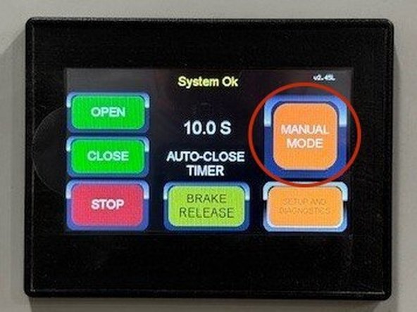
To adjust the level of track retention, first run the door open, and place it in "Manual Mode" from the operator screen.
-
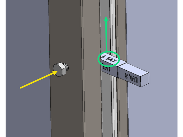
To use the gauge, orient the face with desired gapping callout towards the ceiling, and insert it into the track mouth at each vertical track adjustment point.
-
Each vertical track will have no more than 4 adjustment points.
-
Using a 1/2in Wrench, tighten the bolt (clockwise) until the track mouth is slightly snug around the gauge.
-
DO NOT OVERTIGHTEN. The gauge should be able to slide in and out of the track mouth without much effort.
-
Repeat these steps at each adjustment point/location.
-
-
-
Your door is ready to use!
-
IF YOU HAVE ANY QUESTIONS OR NEED SUPPORT, CALL US @ 262-746-3374.
-



Team
