
-
-
Technical Support Contacts:
-
Phone: 262-746-3374
-
Email: techsupport@goffscw.com
-
Website: http://www.goffsenterprises.com
-
-
-
The Door Header must be level for the Door to operate properly.
-
Check the door opening Header for level, and adjust the installation accordingly.
-
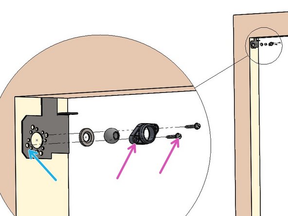
Locate the Left Hand Header Mounting Bracket, and prepare to work on the upper Left of the Door Opening.
-
Align the top edge of the Bracket to the upper surface of the Door Opening.
-
Align the back edge of the Bracket to the Back Edge of the Door Opening.
-
Measure the Hole Centers on the Bearing Block to help determine which Mounting Holes will be used in the Bracket.
-
Transfer two hole locations onto the Mounting Surface.
-
-
-
Prepare the Mounting Surface for Wall Mounting Hardware.
-
Insert your Wall Mounting Hardware through Idler Bearing assembly (3 pieces).
-
Then through the Left Hand Header Mounting Bracket, into the Mounting Surface.
-
-
-
After Mounting the Drive-Side Bracket (by-itself) directly into the Jamb, Use 2 people, and 2 ladders at minimum.
-
Raise the Header Assembly
-
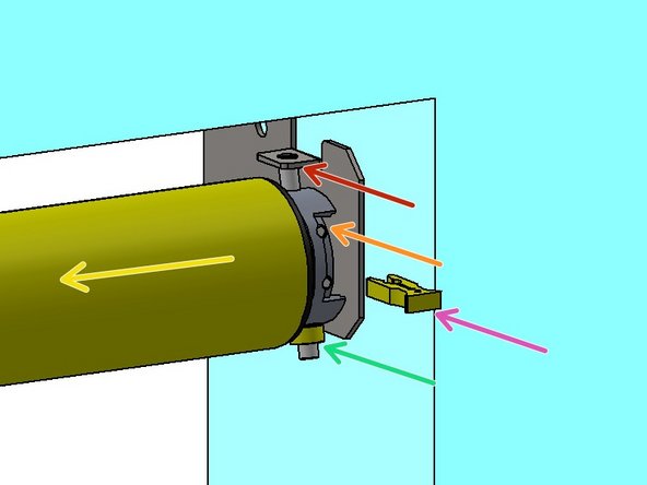
Insert the Idler Shaft into the installed Idler Bearing Assembly at Upper Left.
-
At the right side, orient the Switches toward the Front.
-
Insert the Upper Motor Peg fully into upper hole of R.H. Header Mounting Bracket.
-
Slip the plastic Ring onto Lower Motor Peg.
-
Insert the Lower Motor Peg into the Lower hole on the Header Mounting Bracket.
-
Insert the plastic Clip onto the Upper Motor Peg to fill space between the Bracket and Motor.
-
-
-
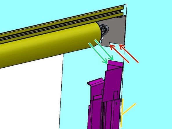
Locate the Left Hand Track (Marked LH).
-
Align the mating surfaces of the Track Transition Bracket -
-
-to the Header Mounting Bracket.
-
Plumb Track Assembly (Front to Back).
-
Use a 2nd Person to hold the Track in place.
-
Transfer the Mounting Hole locations onto the Mounting Surface.
-
-
-
Prepare the Hole locations for the Mounting Hardware.
-
Check for Plumb before securing the Track tightly to the Mounting Surface.
-
Repeat process for the other Track assembly.
-
-
-
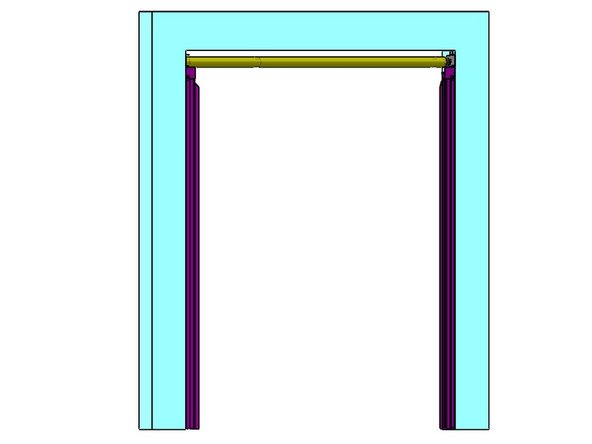
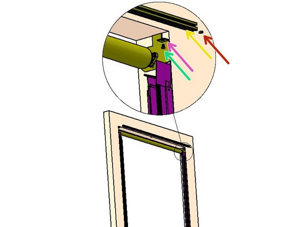
The Valance Assembly Mounts on top of the bent Flanges of the installed Header Mounting Brackets.
-
The Valance Beam has pre-installed Mounting Hardware.
-
Remove two Screws from the Valance Beam.
-
Leave the Nuts in the groove near the ends.
-
Lift the Beam into place on top of the Flanges.
-
With a Screwdriver, move the Nuts into place above the Mounting Flange holes.
-
Re-install the Screws through the hole in each Mounting Flange, then secure them in the captured Nuts.
-


Team
